DS1921H/Z
Stop Mission
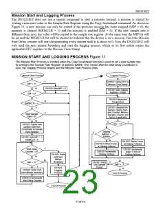
The DS1921H/Z does not have a special command to stop a mission. A mission can be stopped at any
time by writing to any address in the range of 0200h to 0213h or by writing the MIP bit of the Status
Register at address 0214h to 0. Either approach involves the use of the Copy Scratchpad command. There
is no need for the Mission Start Delay to expire before a mission can be stopped (see Figure 11).
MEMORY ACCESS CONFLICTS
While a mission is in progress, periodically a temperature sample is taken and stored in the datalog, his-
togram, and potentially alarm memory. This "internal activity" has priority over a Read Memory or Read
Memory with CRC access to these pages. If a conflict occurs, the data read may be invalid, even if the
CRC value matches the data. To ensure that the data read is valid, it is recommended to first read the SIP
bit of the Status Register. If the SIP bit is set, delay reading the datalog, histogram, and alarm memory
until SIP is 0. The interference is more likely to be seen with a high sample rate (1 sample every minute).
Since all mission samples occur on the seconds rollover (59 to 00), memory conflicts can be avoided by
first reading the RTC seconds counter. For example, if it takes two seconds to read the datalog, then avoid
starting the memory read if the seconds counter is 58, 59 or 00. Alternatively, one can read the affected
memory section twice and accept the data only if both readings match. In any case, when writing driver
software, it is important to know about the possibility of interference and to take measures to work
around it.
1-WIRE BUS SYSTEM
The 1-Wire bus is a system that has a single bus master and one or more slaves. In all instances the
DS1921H/Z is a slave device. The bus master is typically a microcontroller. The discussion of this bus
system is broken down into three topics: hardware configuration, transaction sequence, and 1-Wire
signaling (signal types and timing). The 1-Wire protocol defines bus transactions in terms of the bus state
during specific time slots that are initiated on the falling edge of sync pulses from the bus master. For a
more detailed protocol description, refer to Chapter 4 of the Book of DS19xx iButton Standards.
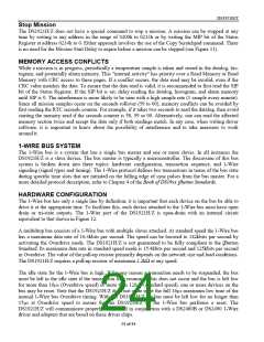
HARDWARE CONFIGURATION
The 1-Wire bus has only a single line by definition; it is important that each device on the bus be able to
drive it at the appropriate time. To facilitate this, each device attached to the 1-Wire bus must have open
drain or tri-state outputs. The 1-Wire port of the DS1921H/Z is open-drain with an internal circuit
equivalent to that shown in Figure 12.
A multidrop bus consists of a 1-Wire bus with multiple slaves attached. At standard speed the 1-Wire bus
has a maximum data rate of 16.3kbits per second. The speed can be boosted to 142kbits per second by
activating the Overdrive mode. The DS1921H/Z is not guaranteed to be fully compliant to the iButton
Standard. Its maximum data rate in standard speed mode is 15.4kbits per second and 125kbits per second
in Overdrive. The value of the pull-up resistor primarily depends on the network size and load conditions.
The DS1921H/Z requires a pull-up resistor of maximum 2.2kΩ at any speed.
The idle state for the 1-Wire bus is high. If for any reason a transaction needs to be suspended, the bus
must be left in the idle state if the transaction is to resume. If this does not occur and the bus is left low
for more than 16µs (Overdrive speed) or more than 120µs (standard speed), one or more devices on the
bus may be reset. Note that the DS1921H/Z does not quite meet the full 16µs maximum low time of the
normal 1-Wire bus Overdrive timing. With the DS1921H/Z the bus must be left low for no longer than
15µs at Overdrive speed to ensure that no DS1921H/Z on the 1-Wire bus performs a reset. The
DS1921H/Z will communicate properly when used in conjunction with a DS2480B or DS2490 1-Wire
driver and adapters that are based on these driver chips.
24 of 44

 DALLAS [ DALLAS SEMICONDUCTOR ]