DS1685/DS1687 3V/5V Real-Time Clocks
SQUARE-WAVE OUTPUT SELECTION
The SQW pin can be programmed to output a variety of frequencies divided down from the 32.768kHz crystal tied
to X1 and X2. The square-wave output is enabled and disabled by the SQWE bit in Register B or the E32K bit in
extended register 4Bh. If the square wave is enabled (SQWE = 1 or E32K = 1), then the output frequency is
determined by the settings of the E32K bit in Extended Register 4Bh and by the RS3–0 bits in Register A. If E32K
= 1, then a 32.768kHz square wave is output on the SQW pin regardless of the settings of RS3–0 and SQWE.
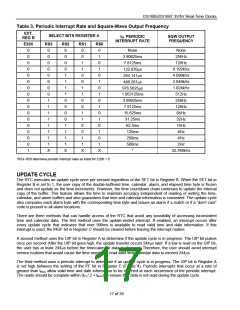
If E32K = 0, then the square-wave output frequency is determined by the RS3–0 bits. These bits control a 1-of-16
decoder, which selects one of 13 taps that divide the 32.768kHz frequency. The RS3–0 bits establish the SQW
output frequency as shown in Table 3. In addition, RS3–0 bits control the periodic interrupt selection as described
below.
If E32K = 1 and the auxiliary-battery enable bit (ABE, bank 1; register 04BH) is enabled, and voltage is applied to
V
BAUX, then the 32kHz square-wave output signal is output on the SQW pin in the absence of VCC. This facility is
provided to clock external power management circuitry. If any of the above requirements are not met, no square-
wave output signal is generated on the SQW pin in the absence of VCC.
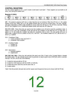
A pattern of 01X in the DV2, DV1, and DV0 bits respectively turns the oscillator on and enables the countdown
chain. Note that this is different than the DS1287, which required a pattern of 010 in these bits. DV0 is now a “don’t
care” because it is used for selection between register banks 0 and 1.
A pattern of 11X turns the oscillator on, but the oscillator’s countdown chain is held in reset, as it was in the
DS1287. Any other bit combination for DV2 and DV1 keeps the oscillator off.
OSCILLATOR CONTROL BITS
When the DS1687 is shipped from the factory, the internal oscillator is turned off. This feature prevents the lithium
energy cell from being used until it is installed in a system. A pattern of 01X in bits 4 through 6 of Register A turns
the oscillator on and enables the countdown chain. A pattern of 11X turns the oscillator on, but holds the
countdown chain of the oscillator in reset. All other combinations of bits 4 through 6 keep the oscillator off.
PERIODIC INTERRUPT SELECTION
The periodic interrupt causes the IRQ pin to go to an active state from once every 500ms to once every 122µs.
This function is separate from the alarm interrupt, which can be output from once per second to once per day. The
periodic interrupt rate is selected using the same RS3–0 bits in Register A, which select the square-wave
frequency (Table 3). Changing the bits affects both the square-wave frequency and the periodic-interrupt output.
However, each function has a separate enable bit in Register B. The SQWE and E32K bits control the square-
wave output. Similarly, the periodic interrupt is enabled by the PIE bit in Register B. The periodic interrupt can be
used with software counters to measure inputs, create output intervals, or await the next needed software function.
16 of 39

 DALLAS [ DALLAS SEMICONDUCTOR ]