DS1685/DS1687 3V/5V Real-Time Clocks
NV RAM—RTC
The 242 general-purpose NV RAM bytes are not dedicated to any special function within the DS1685/DS1687.
They can be used by the application program as nonvolatile memory and are fully available during the update
cycle.
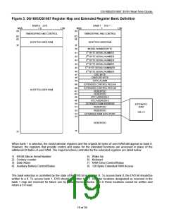
The user RAM is divided into two separate memory banks. When the bank 0 is selected, the 14 RTC registers and
114 bytes of user RAM are accessible. When bank 1 is selected, an additional 128 bytes of user RAM are
accessible through the extended RAM address and data registers.
INTERRUPT CONTROL
The DS1685/DS1687 includes six separate, fully automatic sources of interrupt for a processor:
1) Alarm Interrupt
2) Periodic Interrupt
3) Update-Ended Interrupt
4) Wake-Up Interrupt
5) Kickstart Interrupt
6) RAM Clear Interrupt
The conditions that generate each of these independent interrupt conditions are described in detail in other
sections of this text. This section describes the overall control of the interrupts.
The application software can select which interrupts, if any, are to be used. There are a total of 6 bits, including 3
bits in Register B and 3 bits in Extended Register 4B, that enable the interrupts. The extended register locations
are described later. Writing a logic 1 to an interrupt-enable bit permits that interrupt to be initiated when the event
occurs. A logic 0 in the interrupt enable bit prohibits the IRQ pin from being asserted from that interrupt condition. If
an interrupt flag is already set when an interrupt is enabled, IRQ is immediately set at an active level, even though
the event initiating the interrupt condition might have occurred much earlier. As a result, there are cases where the
software should clear these earlier generated interrupts before first enabling new interrupts.
When an interrupt event occurs, the relating flag bit is set to a logic 1 in Register C or in Extended Register 4A.
These flag bits are set regardless of the setting of the corresponding enable bit located either in Register B or in
Extended Register 4B. The flag bits can be used in a polling mode without enabling the corresponding enable bits.
However, care should be taken when using the flag bits of Register C as they are automatically cleared to 0
immediately after they are read. Double latching is implemented on these bits so that set bits remain stable
throughout the read cycle. All bits that were set are cleared when read and new interrupts that are pending during
the read cycle are held until after the cycle is completed. One, two, or three bits can be set when reading Register
C. Each used flag bit should be examined when read to ensure that no interrupts are lost.
The flag bits in Extended Register 4A are not automatically cleared following a read. Instead, each flag bit can be
cleared to 0 only by writing 0 to that bit.
When using the flag bits with fully enabled interrupts, the IRQ line is driven low when an interrupt flag bit is set and
its corresponding enable bit is also set. IRQ is held low as long as at least one of the six possible interrupt sources
has its flag and enable bits both set. The IRQF bit in Register C is a 1 whenever the IRQ pin is being driven low as
a result of one of the six possible active sources. Therefore, determination that the DS1685/DS1687 initiated an
interrupt is accomplished by reading Register C and finding IRQF = 1. IRQF remains set until all enabled interrupt
flag bits are cleared to 0.
15 of 39

 DALLAS [ DALLAS SEMICONDUCTOR ]