50
8Bit Single Chip Microcontroller
DMC73C168
3) Set the START FLAG (ADCNTL register bit 6) to "1"
Then A/D conversion starts.
4) The conversion data is transfered to the ADDATA register, after A/D conversion completed.
Then the READY FLAG (ADCNTL register bit 7) set to "1" automatically.
5) Can read the ADDATA register.
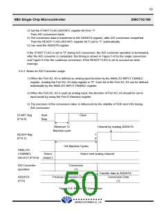
If the START FLAG is set to "0" during A/D conversion, the A/D converter operation is terminated,
after the A/D converter is completed, this timing is shown in Figure 5-8 for the single conversion
and Figure 5-9 for the continous conversion. If the READY FLAG is set to occured as other
Interrupt.
5.6.3 Notes for A/D Converter usage
1) When the Port A2, A3 is defined as analog input function by the ANALOG INPUT ENABLE
register, reading the Port A2, A3 data register is "0". Each bit of the Port A2, A3 can be defined
individually by the ANALOG INPUT ENABLE register.
2) When the Port A2, A3 is used as analog input, the direction of Port A2, A3 should be set to
input mode by using the Port A Direction register.
3) The precision of the conversion value is influenced by the stability of VDD and VSS during
A/D conversion.
START flag
(P14.6)
Start
Stop
Clear
Minimum 12
Cleared by reading ADDATA
Machine cycle
READY flag
(P14.7)
1
0
144 Machine Cycles
Select next analog channel
ANALOG
CHANNEL
Select
Data(1)
SELECT (P14.0)
A/D Converter
operation
Conversion
(1)
Transfer data to ADDATA
Conversion Data
(1)
ADDATA
(P15)
Previous Conversion Data
Figure 5-8. Single A/D Conversion
£Ä£Á£Å£×£Ï £Ï
DAEWOO ELECTRONICS CO., LTD.

 DAEWOO [ DAEWOO Electronic Components ]