49
8Bit Single Chip Microcontroller
DMC73C168
Bit 1 : Bit 5 Not used.
Bit 6 : START FLAG
Even through the START FLAG is set to "1" or "0" during A/D conversion, the START
FLAG is ignored till the current conversion is completed.
WRITE
START A/D Converter Start/Stop Control bit.
0 = Stop A/D conversion
1 = Start A/D conversion
Bit 7 : READY FLAG
When the analog conversion data is set to ADDATA register (P16), the READY FLAG
will be set to "1". Then the ADDATA register can be read by software. After the ADDATA
register is read, the READY FLAG will be set to "0" automatically.
READ
0 = No operation or Incomplete conversion
1 = Complete conversion
WRITE
0 = Ineffect
1 = Clear READY FLAG
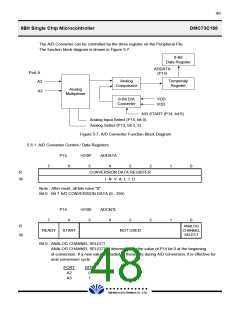
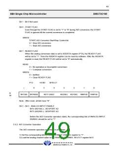
P13
>010D
5
APSLCT
4
6
3
2
1
0
7
R
W
INT3SE INT40SE
NOT USED
AD2SEL AD1SEL AMIFSE FMIFSE
Note : After reset, all bits have "0"
Bit 2 - Bit 3 : ANALOG INPUT ENABLE
BIT2 (AD1SEL) : AD1/PORT A2
BIT3 (AD2SEL) : AD2/PORT A3
Before the A/D Converter operation starts, the corresponding bits of ANALOG INPUT
ENABLE should be set to "1".
5.6.2 A/D Converter Operation
The A/D converter operation procedure is as follows.
1) Set the corresponding bits of ANALOG INPUT ENABLE register to "1".
2) Load the analog channel value to the ANALOG CHANNEL SELECT register bit 0.
£Ä£Á£Å£×£Ï £Ï
DAEWOO ELECTRONICS CO., LTD.

 DAEWOO [ DAEWOO Electronic Components ]