SL811HS
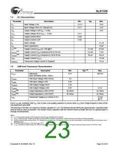
7.4
DC Characteristics
Parameter
Description
Min.
–0.3 V
2.0 V
Typ.
Max.
0.8V
6.0V
0.4V
VIL
Input Voltage LOW
VIH
VOL
VOH
IOH
IOL
Input Voltage HIGH (5V Tolerant I/O)
Output Voltage LOW (IOL = 4 mA)
Output Voltage HIGH (IOH = –4 mA)
Output Current HIGH
2.4 V
4 mA
4 mA
Output Current LOW
ILL
Input Leakage
±1 µA
10 pF
25 mA
5 mA
CIN
Input Capacitance
[16]
ICC
Supply Current (VDD) inc USB @FS
Supply Current (VDD) Suspend w/Clk & Pll Enb
Supply Current (VDD) Suspend no Clk & Pll Dis
21 mA
4.2 mA
50 µA
[17]
[18]
ICCsus1
ICCsus2
IUSB
60 µA
10 mA
10 µA
Supply Current (VDD1
)
IUSBSUS
Transceiver Supply Current in Suspend
7.5
USB Host Transceiver Characteristics
Parameter
Description
Min.
Typ.[19]
Max.
VIHYS
Differential
0.2V
200 mV
Input Sensitivity (Data+, Data–)
USB Input Voltage HIGH Driven
USB Input Voltage LOW
VUSBIH
VUSBIL
VUSBOH
VUSBOL
2.0
0.8V
USB Output Voltage HIGH
2.0V
USB Output Voltage LOW
0.0V
0.3 V
[20]
ZUSBH
Output Impedance HIGH STATE
Output Impedance LOW STATE
Transceiver Supply p-p Current (3.3V)
36 Ohms
36 Ohms
42 Ohms
42 Ohms
[20]
ZUSBL
IUSB
10 mA
@ FS
Every VDD pin, including USB VDD, has to have a decoupling capacitor to ensure clean VDD (free of high-frequency noise) at the
chip input point (pin) itself.
The best way to do this is to connect a ceramic capacitor (0.1 µF, 6V) between the pin itself and a good ground. Capacitor leads
must be kept as short as possible. Use surface mount capacitors with the shortest traces possible (the use of a ground plane is
strongly recommended).
Notes:
16. ICC measurement includes USB Transceiver current (IUSB) operating at Full Speed.
17.
18.
I
CCsus1 measured with 12-MHz Clock Input and Internal PLL enabled. Suspend set –(USB transceiver and internal Clocking disabled).
ICCsus2 measured with external Clock, PLL disabled, and Suspend set. For absolute minimum current consumption, ensure that all inputs to the device are at
static logic level.
19. All typical values are VDD = 3.3V and TAMB= 25°C.
20. impedance values includes an external resistor of 24 Ohms ± 1% (SL811HS revision 1.2 requires external resistor values of 33 Ohms ±1%).
Document #: 38-08008 Rev. *A
Page 23 of 29

 CYPRESS [ CYPRESS ]