CY8C9520A, CY8C9540A
CY8C9560A
AC I2C Specifications
Table 27 lists guaranteed maximum and minimum specifications for the voltage and temperature ranges: 4.75V to 5.25V and -40°C
≤ TA ≤ 85°C, or 3.0V to 3.6V and -40°C ≤ TA ≤ 85°C, respectively. Typical parameters apply to 5V and 3.3V at 25°C and are for design
guidance only or unless otherwise specified.
Table 27. AC Characteristics of the I2C SDA and SCL Pins
Standard Mode
Min Max
100
Fast Mode
Min Max
Symbol
Description
SCL clock frequency
Units
kHz
Notes
FSCLI2C
0
0
–
–
THDSTAI2C Hold time (repeated) START condition. After 4.0
this period, the first clock pulse is generated.
–
0.6
μs
TLOWI2C
THIGHI2C
LOW period of the SCL clock
HIGH period of the SCL clock
4.7
4.0
4.7
0
–
–
–
–
–
–
–
1.3
0.6
0.6
0
1003
0.6
1.3
–
–
–
–
–
–
–
μs
μs
μs
μs
ns
μs
μs
TSUSTAI2C Setup time for a repeated START condition
THDDATI2C Data hold time
TSUDATI2C Data setup time
250
4.0
TSUSTOI2C Setup time for STOP condition
TBUFI2C
Bus free time between a STOP and START 4.7
Condition
TSPI2C
Pulse width of spikes are suppressed by the
input filter.
–
–
0
–
ns
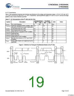
Figure 9. Definition for Timing for Fast/Standard Mode on the I2C Bus
SDA
SCL
TSPI2C
TLOWI2C
TSUDATI2C
THDSTAI2C
TBUFI2C
TSUSTOI2C
TSUSTAI2C
THDDATI2C
THDSTAI2C
THIGHI2C
S
Sr
P
S
Document Number: 38-12036 Rev. *B
Page 19 of 24
[+] Feedback

 CYPRESS [ CYPRESS ]