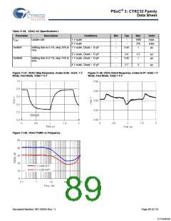
PSoC® 3: CY8C32 Family
Data Sheet
11.3.5 USB
Table 11-42. USB DC Specifications
Parameter
VUSB_5
Description
Conditions
Min
Typ
Max
Units
Device supply for USB operation
USB configured, USB regulator
enabled
4.35
–
5.25
V
VUSB_3.3
VUSB_3
USB configured, USB regulator
bypassed
3.15
2.85
–
–
3.6
3.6
V
V
USB configured, USB regulator
bypassed[41]
IUSB_Configured Device supply current in device active VDDD = 5 V, FCPU = 1.5 MHz
mode, bus clock and IMO = 24 MHz
–
–
–
10
8
–
–
–
mA
mA
mA
V
DDD = 3.3 V, FCPU = 1.5 MHz
IUSB_Suspended Device supply current in device sleep VDDD = 5 V, connected to USB
0.5
mode
host, PICU configured to wake on
USB resume signal
V
DDD = 5 V, disconnected from
–
–
0.3
0.5
–
–
mA
mA
USB host
VDDD = 3.3 V, connected to USB
host, PICU configured to wake on
USB resume signal
VDDD = 3.3 V, disconnected from
–
0.3
–
mA
USB host
11.3.6 Universal Digital Blocks (UDBs)
PSoC Creator provides a library of pre-built and tested standard digital peripherals (UART, SPI, LIN, PRS, CRC, timer, counter, PWM,
AND, OR, and so on) that are mapped to the UDB array. See the component datasheets in PSoC Creator for full AC/DC specifications,
APIs, and example code.
Table 11-43. UDB AC Specifications
Parameter
Description
Conditions
Min
Typ
Max
Units
Datapath Performance
FMAX_TIMER Maximum frequency of 16-bit timer in
a UDB pair
–
–
–
–
–
–
50.01
50.01
50.01
MHz
MHz
MHz
FMAX_ADDER Maximum frequency of 16-bit adder in
a UDB pair
FMAX_CRC
Maximum frequency of 16-bit
CRC/PRS in a UDB pair
PLD Performance
FMAX_PLD Maximum frequency of a two-pass
PLD function in a UDB pair
Clock to Output Performance
tCLK_OUT Propagation delay for clock in to data 25 °C, Vddd ≥ 2.7 V
out, see Figure 11-50.
Propagation delay for clock in to data Worst-case placement, routing,
out, see Figure 11-50. and pin selection
–
–
50.01
MHz
–
–
20
–
25
55
ns
ns
tCLK_OUT
Note
41. Rise/fall time matching (TR) not guaranteed, see USB Driver AC Specifications on page 77.
Document Number: 001-56955 Rev. *J
Page 93 of 119
[+] Feedback

 CYPRESS [ CYPRESS ]