PSoC® 3: CY8C32 Family
Data Sheet
11.2 Device Level Specifications
Specifications are valid for –40 °C ≤ TA ≤ 85 °C and TJ ≤ 100 °C, except where noted. Specifications are valid for 1.71 V to 5.5 V,
except where noted.
11.2.1 Device Level Specifications
Table 11-2. DC Specifications
Parameter
Description
Conditions
Min
Typ
Max
Units
VDDA
Analog supply voltage and input to Analog core regulator enabled
analog core regulator
1.8
–
5.5
V
VDDA
VDDD
VDDD
Analog supply voltage, analog
regulator bypassed
Analog core regulator disabled
Digital core regulator enabled
Digital core regulator disabled
1.71
1.8
1.8
–
1.89
V
V
V
[16]
Digital supply voltage relative to
VSSD
VDDA
Digital supply voltage, digital
regulator bypassed
1.71
1.8
1.89
[17]
[16]
VDDIO
I/IO supply voltage relative to VSSIO
1.71
1.71
–
VDDA
1.89
V
V
VCCA
Direct analog core voltage input
(Analog regulator bypass)
Analog core regulator disabled
Digital core regulator disabled
1.8
VCCD
Direct digital core voltage input
(Digital regulator bypass)
1.71
1.8
1.89
V
[18]
IDD
Active Mode, VDD = 1.71 V–5.5 V
Bus clock off. Execute from CPU
instruction buffer. See “Flash
Program Memory” on page 22.
CPU at 3 MHz
CPU at 6 MHz
CPU at 12 MHz
CPU at 24 MHz
CPU at 48 MHz
T = –40 °C
–
–
–
–
–
–
–
–
–
–
–
–
–
–
–
–
–
–
–
–
–
0.8
–
–
–
–
–
–
–
–
–
–
–
–
–
–
–
–
–
–
–
–
–
mA
mA
mA
mA
mA
mA
mA
mA
mA
mA
mA
mA
mA
mA
mA
mA
mA
mA
mA
mA
T = 25 °C
T = 85 °C
T = –40 °C
T = 25 °C
T = 85 °C
T = –40 °C
T = 25 °C
T = 85 °C
T = –40 °C
T = 25 °C
T = 85 °C
T = –40 °C
T = 25 °C
T = 85 °C
–
1.2
–
–
2.0
–
–
3.5
–
–
6.6
–
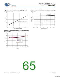
VDD = 3.3 V, T = 25 °C, IMO and bus CPU at 3 MHz
1.4
2.2
3.6
6.4
11.8
clock enabled, ILO = 1 kHz, CPU
executing from flash and accessing
SRAM, all other blocks off, all I/Os
tied low.
CPU at 6 MHz
CPU at 12 MHz
CPU at 24 MHz
CPU at 48 MHz
Notes
16. The power supplies can be brought up in any sequence however once stable VDDA must be greater than or equal to all other supplies.
17. The VDDIO supply voltage must be greater than the maximum analog voltage on the associated GPIO pins. Maximum analog voltage on GPIO pin ≤ VDDIO ≤ VDDA
.
18. The current consumption of additional peripherals that are implemented only in programmed logic blocks can be found in their respective datasheets, available in
PSoC Creator, the integrated design environment. To estimate total current, find CPU current at frequency of interest and add peripheral currents for your particular
system from the device datasheet and component datasheets.
Document Number: 001-56955 Rev. *J
Page 63 of 119
[+] Feedback

 CYPRESS [ CYPRESS ]