CY7C68013A, CY7C68014A
CY7C68015A, CY7C68016A
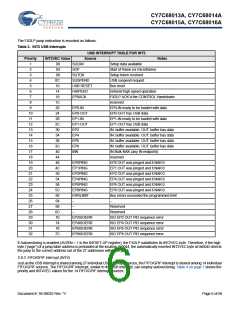
Table 1. Special Function Registers
x
0
1
2
3
4
5
6
7
8
9
A
B
C
D
E
F
8x
IOA
9x
Ax
Bx
IOD
Cx
Dx
Ex
ACC
–
Fx
B
–
IOB
IOC
SCON1
PSW
SP
EXIF
INT2CLR
IOE
SBUF1
–
DPL0
DPH0
DPL1
DPH1
DPS
PCON
TCON
TMOD
TL0
MPAGE
INT4CLR
OEA
OEB
OEC
OED
OEE
–
–
–
–
–
–
–
–
–
–
–
–
–
–
–
–
–
–
–
–
–
–
–
–
–
–
–
–
–
–
–
–
T2CON
–
–
–
–
SCON0
SBUF0
AUTOPTRH1
AUTOPTRL1
reserved
AUTOPTRH2
AUTOPTRL2
reserved
IE
IP
EICON
EIE
–
EIP
–
–
–
–
–
–
–
–
–
–
EP2468STAT
EP01STAT
GPIFTRIG
RCAP2L
RCAP2H
TL2
–
–
TL1
EP24FIFOFLGS
–
–
TH0
EP68FIFOFLGS
–
–
TH1
–
–
GPIFSGLDATH
GPIFSGLDATLX
TH2
–
–
CKCON
–
–
–
–
AUTOPTRSET-UP GPIFSGLDATLNOX
–
–
–
Two control bits in the USBCS (USB Control and Status) register,
control the ReNumeration process: DISCON and RENUM. To
simulate a USB disconnect, the firmware sets DISCON to 1. To
reconnect, the firmware clears DISCON to 0.
2.5 USB Boot Methods
During the power up sequence, internal logic checks the I2C port
for the connection of an EEPROM whose first byte is either 0xC0
or 0xC2. If found, it uses the VID/PID/DID values in the EEPROM
in place of the internally stored values (0xC0), or it boot-loads the
EEPROM contents into internal RAM (0xC2). If no EEPROM is
detected, FX2LP enumerates using internally stored descriptors.
The default ID values for FX2LP are VID/PID/DID (0x04B4,
0x8613, 0xAxxx where xxx = Chip revision).[2]
Before reconnecting, the firmware sets or clears the RENUM bit
to indicate whether the firmware or the Default USB Device
handles device requests over endpoint zero: if RENUM = 0, the
Default USB Device handles device requests; if RENUM = 1, the
firmware services the requests.
Table 2. Default ID Values for FX2LP
Default VID/PID/DID
2.7 Bus-Powered Applications
The FX2LP fully supports bus powered designs by enumerating
with less than 100 mA as required by the USB 2.0 specification.
Vendor ID
Product ID
0x04B4 Cypress Semiconductor
0x8613 EZ-USB FX2LP
2.8 Interrupt System
Device release 0xAnnn Depends on chip revision
(nnn = chip revision where first
silicon = 001)
2.8.1 INT2 Interrupt Request and Enable Registers
FX2LP implements an autovector feature for INT2 and INT4.
There are 27 INT2 (USB) vectors, and 14 INT4 (FIFO/GPIF)
vectors. See EZ-USB Technical Reference Manual (TRM) for
more details.
2.6 ReNumeration
Because the FX2LP’s configuration is soft, one chip can take on
the identities of multiple distinct USB devices.
2.8.2 USB Interrupt Autovectors
When first plugged into USB, the FX2LP enumerates
automatically and downloads firmware and USB descriptor
tables over the USB cable. Next, the FX2LP enumerates again,
this time as a device defined by the downloaded information.
This patented two step process called ReNumeration happens
instantly when the device is plugged in, without a hint that the
initial download step has occurred.
The main USB interrupt is shared by 27 interrupt sources. To
save the code and processing time that is required to identify the
individual USB interrupt source, the FX2LP provides a second
level of interrupt vectoring, called Autovectoring. When a USB
interrupt is asserted, the FX2LP pushes the program counter to
its stack, and then jumps to the address 0x0043 where it expects
to find a “jump” instruction to the USB Interrupt service routine.
Note
2
2. The I C bus SCL and SDA pins must be pulled up, even if an EEPROM is not connected. Otherwise this detection method does not work properly.
Document #: 38-08032 Rev. *V
Page 5 of 66

 CYPRESS [ CYPRESS ]