BCM4330 Preliminary Data Sheet
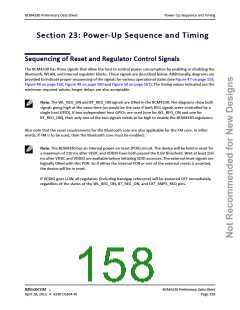
Sequencing of Reset and Regulator Control Signals
Description of Control Signals
• WL_REG_ON: Used by the PMU to power up the WLAN section. It is also OR-gated with the BT_REG_ON
input to control the internal BCM4330 regulators. When this pin is high, the regulators are enabled and
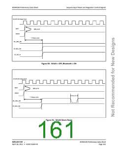
the WLAN section is out of reset. When this pin is low the WLAN section is in reset. A “warm” WLAN reset
can be initiated by driving WL_REG_ON low for at least 10 microseconds (see Figure 51 on page 161). If
both the BT_REG_ON and WL_REG_ON pins are low, the regulators are disabled. Logic High Level: 1.08V–
3.6V. 200k pull-down resistor included.
• BT_REG_ON: Used by the PMU (OR-gated with WL_REG_ON) to power up the internal BCM4330
regulators. If both the BT_REG_ON and WL_REG_ON pins are low, the regulators are disabled. Logic High
Level: 1.08V–3.6V. 200k pull-down resistor included.
• BT_RST_N: Low asserting reset for Bluetooth and FM only. This pin has no effect on WLAN and does not
control any PMU functions. This pin must be driven high or low (not left floating).
In addition, two other input signals control PMU modes:
• When EXT_SMPS_REQ is pulled high, it forces CBUCK to stay on, even when the other regulators are shut
down by WL_REG_ON or BT_REG_ON.
• When WLAN and/or Bluetooth are out of reset and EXT_SMPS_REQ is high, then pulling EXT_PWM_REQ
high makes CBUCK go into PWM mode, even if internal settings from WLAN and/or Bluetooth are
requesting burst mode. During such contention, the request for the higher-power mode wins.
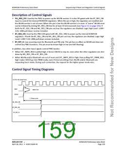
Control Signal Timing Diagrams
32.678 kHz Sleep Clock
VBAT
90% of VH
VDDIO
~ 2 Sleep cycles
WL_REG_ON
BT_REG_ON
BT_RST_N
Figure 47: WLAN = ON, Bluetooth = ON
®
BROADCOM
BCM4330 Preliminary Data Sheet
April 28, 2011 • 4330-DS304-RI
Page 159

 CYPRESS [ CYPRESS ]