2. The 8051 encounters any show stopper error on the endpoint, and sets the stall bit
to tell the host to halt traffic to the endpoint.
The 8051 clears an endpoint’s stall bit under two circumstances:
1. The host sends a “Clear_Feature—Endpoint Stall” request to the specific endpoint.
2. The 8051 receives some other indication from the host that the stall should be
cleared (this is referred to as “host intervention” in the USB Specification).
All stall bits are automatically cleared when the EZ-USB chip ReNumerates .
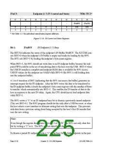
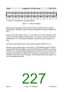
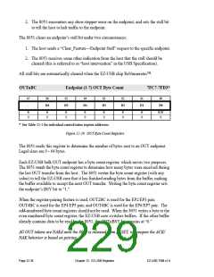
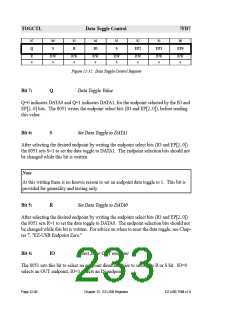
OUTnBC
Endpoint (1-7) OUT Byte Count
7FC7-7FD3*
b7
b6
b5
b4
b3
b2
b1
b0
-
D6
D5
D4
D3
D2
D1
D0
R
0
R
0
R
0
R
0
R
0
R
0
R
0
R/W
0
* See Table 12-5 for individual control/status register addresses.
Figure 12-29. OUT Byte Count Registers
The 8051 reads this register to determine the number of bytes sent to an OUT endpoint.
Legal sizes are 0 - 64 bytes.
Each EZ-USB bulk OUT endpoint has a byte count register, which serves two purposes.
The 8051 reads the byte count register to determine how many bytes were received during
the last OUT transfer from the host. The 8051 writes the byte count register (with any
value) to tell the EZ-USB core that it has finished reading bytes from the buffer, making
the buffer available to accept the next OUT transfer. Writing the byte count register sets
the endpoint’s BSY bit to “1.”
When the register-pairing feature is used, OUT2BC is used for the EP2/EP3 pair,
OUT4BC is used for the EP4/EP5 pair, and OUT6BC is used for the EP6/EP7 pair. The
odd-numbered byte count registers should not be used. When the 8051 writes a byte to the
even numbered byte count register, the EZ-USB core switches buffers. If the other buffer
already contains data to be read by the 8051, the OUTnBSY bit remains at “0.”
All OUT tokens are NAKd until the 8051 is released from RESET, whereupon the ACK/
NAK behavior is based on pairing.
Page 12-36
Chapter 12. EZ-USB Registers
EZ-USB TRM v1.9

 CYPRESS [ CYPRESS ]