TOGCTL
Data Toggle Control
7FD7
b7
b6
b5
b4
b3
b2
b1
b0
Q
S
R
IO
0
EP2
EP1
EP0
R
x
R/W
x
R/W
x
R/W
x
R/W
x
R/W
x
R/W
x
R/W
x
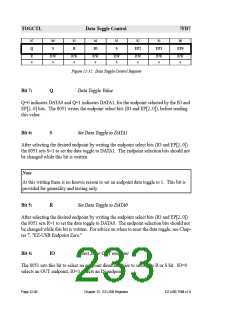
Figure 12-32. Data Toggle Control Register
Bit 7:
Q
Data Toggle Value
Q=0 indicates DATA0 and Q=1 indicates DATA1, for the endpoint selected by the IO and
EP[2..0] bits. The 8051 writes the endpoint select bits (IO and EP[2..0]), before reading
this value.
Bit 6:
S
Set Data Toggle to DATA1
After selecting the desired endpoint by writing the endpoint select bits (IO and EP[2..0])
the 8051 sets S=1 to set the data toggle to DATA1. The endpoint selection bits should not
be changed while this bit is written.
Note
At this writing there is no known reason to set an endpoint data toggle to 1. This bit is
provided for generality and testing only.
Bit 5:
R
Set Data Toggle to DATA0
After selecting the desired endpoint by writing the endpoint select bits (IO and EP[2..0])
the 8051 sets R=1 to set the data toggle to DATA0. The endpoint selection bits should not
be changed while this bit is written. For advice on when to reset the data toggle, see Chap-
ter 7, "EZ-USB Endpoint Zero."
Bit 4:
IO
Select IN or OUT endpoint
The 8051 sets this bit to select an endpoint direction prior to setting its R or S bit. IO=0
selects an OUT endpoint, IO=1 selects an IN endpoint.
Page 12-40
Chapter 12. EZ-USB Registers
EZ-USB TRM v1.9

 CYPRESS [ CYPRESS ]