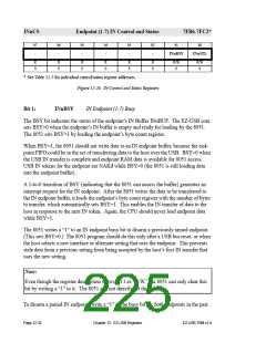
INnCS
Endpoint (1-7) IN Control and Status
7FB6-7FC2*
b7
b6
b5
b4
b3
b2
b1
b0
-
-
-
-
-
-
INnBSY
INnSTL
R
0
R
0
R
0
R
0
R
0
R
0
R/W
0
R/W
0
* See Table 12-5 for individual control/status register addresses.
Figure 12-26. IN Control and Status Registers
Bit 1:
INnBSY
IN Endpoint (1-7) Busy
The BSY bit indicates the status of the endpoint’s IN Buffer INnBUF. The EZ-USB core
sets BSY=0 when the endpoint’s IN buffer is empty and ready for loading by the 8051.
The 8051 sets BSY=1 by loading the endpoint’s byte count register.
When BSY=1, the 8051 should not write data to an IN endpoint buffer, because the end-
point FIFO could be in the act of transferring data to the host over the USB. BSY=0 when
the USB IN transfer is complete and endpoint RAM data is available for 8051 access.
USB IN tokens for the endpoint are NAKd while BSY=0 (the 8051 is still loading data
into the endpoint buffer).
A 1-to-0 transition of BSY (indicating that the 8051 can access the buffer) generates an
interrupt request for the IN endpoint. After the 8051 writes the data to be transferred to
the IN endpoint buffer, it loads the endpoint’s byte count register with the number of bytes
to transfer, which automatically sets BSY=1. This enables the IN transfer of data to the
host in response to the next IN token. Again, the CPU should never load endpoint data
while BSY=1.
The 8051 writes a “1” to an IN endpoint busy bit to disarm a previously armed endpoint.
(This sets BSY=0.) The 8051 program should do this only after a USB bus reset, or when
the host selects a new interface or alternate setting that uses the endpoint. This prevents
stale data from a previous setting from being accepted by the host’s first IN transfer that
uses the new setting.
Note:
Even though the register description shows bit 1 as “R/W,” the 8051 can only clear this
bit by writing a “1” to it. The 8051 can not directly set this bit.
To disarm a paired IN endpoint, write a “1” to the busy bit for both endpoints in the pair.
Page 12-32
Chapter 12. EZ-USB Registers
EZ-USB TRM v1.9

 CYPRESS [ CYPRESS ]