CY7C1359A/GVT71256T18
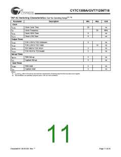
TAP AC Switching Characteristics Over the Operating Range[18, 19]
Parameter
Clock
Description
Min.
Max
Unit
tTHTH
Clock Cycle Time
Clock Frequency
Clock HIGH Time
Clock LOW Time
20
ns
MHz
ns
fTF
50
tTHTL
8
8
tTLTH
ns
Output Times
tTLQX
TCK LOW to TDO Unknown
TCK LOW to TDO Valid
TDI Valid to TCK HIGH
TCK HIGH to TDI Invalid
0
ns
ns
ns
ns
tTLQV
10
tDVTH
5
5
tTHDX
Set-up Times
tMVTH
TMS Set-up
5
5
ns
ns
tCS
Capture Set-up
Hold Times
tTHMX
TMS Hold
5
5
ns
ns
tCH
Capture Hold
Notes:
18. tCS and tCH refer to the set-up and hold time requirements of latching data from the boundary scan register.
19. Test conditions are specified using the load in TAP AC Test Conditions.
Document #: 38-05120 Rev. **
Page 11 of 24

 CYPRESS [ CYPRESS ]