Crane Aerospace & Electronics Power Solutions
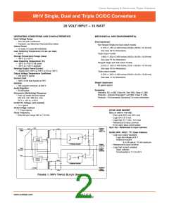
MHV Single, Dual and Triple DC/DC Converters
28 VOLT INPUT – 15 WATT
1
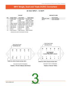
Positive Input
9
MHV
Sync In
28V
2
Inhibit (pin 8 on triple
output models)
10 Input Common
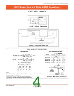
FIGURE 4: TYPICAL CONNECTIONS
1
5
2
1
Positive Output
Positive Input
Positive Input
FMC-461
MHV
28V
or FMH-461
EMI FILTER
4
10 Input Common
Input Common
Output Common
3
6, 7, 8
Case*
Chassis Ground
*The case ground connection should be as low an impedance as possible to minimize EMI.
Direct contact of baseplate to chassis ground provides the lowest impedance.
FIGURE 5: EMI FILTER CONNECTION
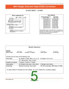
TRIM – SINGLE OUTPUT MODELS ONLY
Calculated Trim
Quick Reference Trim Table
% VOUT NOMINAL
MODEL
(V – 2.5)
110 106 102
95
90
80
o
Trim down: R (kΩ) =
A – B
T
(
(
)
)
R
(R ) k ohms
TRIM (
T
V
V
– V
o nominal
0
MHV283R3S 18
36
20
19
21
128
81
116 177
4
23
n/a n/a
5
67
2.5A
V
MHV2805S
MHV2812S
MHV2815S
8
n/a
0.3
n/a
11
28
Trim up:
R
(kΩ) =
–B
T
o – o nominal
122 255 104
V = desired output voltage
o
RT
Formula Values by Model
3.3V 5V
12V 15V
3
TRIM
TRIM DOWN
A
B
3.7
10
3.7
10
14
30
18.2
30
5
+V
O
MHV
SINGLE
OUTPUT
Notes
4
OUTPUT
COMMON
If calculated result is a negative value, the desired output voltage is outside the allowed trim range.
TRIM UP
Calculated values of R are 15%.
T
When trimming up, do not exceed the maximum output power.
When trimming down, do not exceed the maximum output current.
FIGURE 6: MHV SINGLE OUTPUTTRIM
www.craneae.com
Page 4 of 14
Rev D- 20060710

 CRANE [ Crane Aerospace & Electronics. ]