Crane Aerospace & Electronics Power Solutions
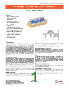
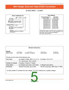
MHV Single, Dual and Triple DC/DC Converters
28 VOLT INPUT – 15 WATT
OPERATING CONDITIONS AND CHARACTERISTICS
MECHANICAL AND ENVIRONMENTAL
Input Voltage Range
• 16 to 50 VDC continuous
• Transient: see Electrical Characteristics tables
Output Power
Size (maximum)
Non-flanged Single and dual output models
2.125 x 1.125 x 0.400 inches (53.98 x 28.58 x 10.16 mm)
See case H2 for dimensions.
• 15 watts (10 watts MHV283R3S)
Lead Soldering Temperature (10 sec per lead)
• 300°C
Triple output models
Storage Temperature Range (Case)
• –65°C to +150°C
1.950 x 1.350 x 0.405 inches (49.53 x 34.29 x 10.29 mm)
See case F1 for dimensions.
Case Operating Temperature (Tc)
• –55°C to +125°C full power
• –55°C to +130°C absolute
Derating Output Power/Current
• Linearly from 100% at 125°C to 0% at 130°C
Output Voltage Temperature Coefficient
• 100 ppm/°C typical
Flanged Single and dual output models
2.910 x 1.125 x 0.400 inches (73.91 x 28.58 x 10.16 mm)
See case K3 for dimensions.
Triple output models
2.720 x 1.350 x 0.405 inches (69.09 x 34.29 x 10.29 mm)
See case J1 for dimensions.
Current Limit
• 130% of full load typical at 25°C
Isolation
Weight (maximum)
60 grams typical
• 100 megohm minimum at 500 V
Audio Rejection
Screening
• 30 dB typical
Standard, ES, or 883 (Class H). See “883, Class H, QML
Products – Element Evaluation” and “883, Class H, QML
Products – Environmental Screening” for more information.
Conversion (Switching) Frequency
• Free run mode 300 kHz typical
245 kHz. min, 355 kHz. max
@ Tc = -55° to +125°C
Inhibit Pin Voltage (unit enabled)
• 11 V typical
Undervoltage Lockout
• 7 V input typical
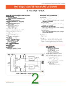
SYNC AND INHIBIT
Clock Frequency
Sync In (490 to 710 kHz)
• External sync range 490 to 710 kHz.
• Duty cycle 40% min, 60% max
• Logic low 0.8 V max
• Logic high 4.5 V min, 10 V max
• Referenced to input common
• If not used, leave unconnected
Sync Out - Referenced to input common
0o
Positive
Positive
Input
Output,
Main (+5)
Inhibit (INH1, INH2) : TTL Open Collector
• Logic low (output disabled)
Logic low voltage ≤0.8 V
Inhibit pin current
PWM CM
Controller
8.4 mA typical, 10 mA maximum
Feedback Isolator
Output
Common
• Referenced to input common
• Logic high (output enabled)
Positive
Input
Common
Output,
Open collector
Auxiliary
Unconnected or 11.5 to 50 V
Sync.
PWM CM
Controller
Feedback Isolator
180o
Negative
Output,
Auxiliary
FIGURE 1: MHV TRIPLE BLOCK DIAGRAM
www.craneae.com
Page 2 of 14
Rev D- 20060710

 CRANE [ Crane Aerospace & Electronics. ]