CTCSS tone @
30mvrms
CTCSS tone
generator
.1uF
100K
100K
Noise generator @
75mvrms, Band limited
6khz gaussian
Noise
generator
.1uF
1khz sine wave @
300mvrms
Audio signal
generator
100K
+Vdd
-
100K
To RXIN and
SINAD meter
.1uF
+
+Vdd
100K
.1uF
Audio Opamp
741 or similar
100K
GND
GND
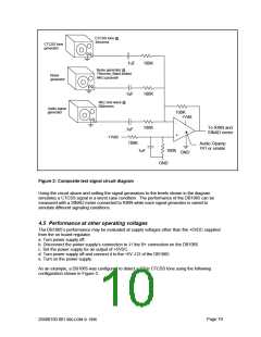
Figure 2: Composite test signal circuit diagram
Using the circuit above and setting the signal generators to the levels shown in the diagram
simulates a CTCSS signal in a worst case condition. The performance of the DB1065 can be
measured with a SINAD meter connected to RXIN while each signal generator is varied to
simulate different signaling conditions.
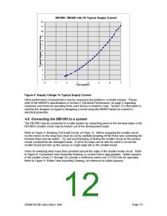
4.5 Performance at other operating voltages
The DB1065’s performance may be evaluated at supply voltages other than the +5VDC supplied
from the on board regulator.
a. Turn power supply off.
b. Disconnect the power supply’s connection to J1 the B+ connection on the DB1065.
c. Set the power supply for an output of +5VDC.
d. Turn power supply off and connect it to the +5V J12 of the DB1065.
e. Turn on the power supply.
As an example, a DB1065 was configured to detect a 67Hz CTCSS tone using the following
configuration shown in Figure 3.
Page 10
20480150.001 MX-COM ꢀ 1996

 CMLMICRO [ CML MICROCIRCUITS ]