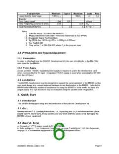
Characteristic
Minimum
Typical
Maximum
Units
Note
Lower Decode Band Edge
1.005 F
i-1
.995 F
i
Hz
3,6
Encoder
Tone Output Level
Tone Frequency Accuracy (f error)
548
-0.30
775
2
mVrms
0.30 %f
o
Total Harmonic Distortion
5
%THD
Notes
1
2
3
4
Valid for +5VDC on Vdd to the MX465 IC.
Measured referenced to 0dB= 1KHz tone referenced to 300 mVrms
Composite Signal Test Condition
f >100Hz (for 100 Hz>f >67Hz: t=100/f Hz X 250ms)
0
0
0
5
6
Per TIA/EIA-603
Only for the F in TIA /EIA-603, where F is the program tone.
i
i
2.3 Prerequisites and Required Equipment
2.3.1 Prerequisites
In order to effectively use the DB1065 Development Kit, the user should refer to the MX-COM
data sheet for the MX465.
2.3.2 Power Supply
A user provided +12VDC regulated power supply is required to power the development card
when connected to the B+ input. A regulated +5VDC supply is used when powering the DB1065
from the +5V input.
2.4 Limitations
The DB1065 development board is designed to support the serial operation of the MX465 but the
user must design and connect external hardware to use this function in the MX465. Refer to the
MX465 data bulletin for additional assistance for using the MX465 in serial mode. All input and
output analog and logic functions may be evaluated using the parallel mode of operation.
3. Quick Start
3.1 Introduction
This section allows quick setup and test verification of the DB1065 Development Kit.
3.2 First...
Review sections 1.4, Handling Precautions; 1.5, Unpacking and 2.4, Limitations sections above.
(Quick start?!!) Don’t worry, those sections are very short and help you to avoid damaging the
DB1065 or your equipment.
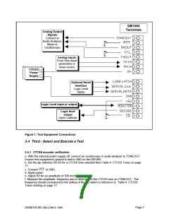
3.3 Second - Setup
a. Connect a +12VDC power supply to B+ and GND.
b. Refer to Figure 1: Test Equipment Connections, on page 7 and Figure 7: DB1065 Schematic,
on page 20 to connect test equipment to the DB1065 development board.
Page 6
20480150.001 MX-COM ꢀ 1996

 CMLMICRO [ CML MICROCIRCUITS ]