5. Hardware
5.1 Introduction
This section describes the PCB hardware and its adjustment.
5.2 Description
5.2.1 Functional Layout of Circuitry
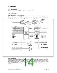
The block diagram of the MX465 shown below shows internal connections to the MX465. Refer
to Figure 7: DB1065 Schematic, on page 20 for external circuitry on the DB1065 circuit board.
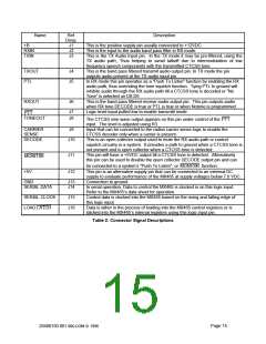
5.2.2 Connectors
Clamping connectors are distributed around the perimeter of the DB1065 motherboard as shown
in Figure 8: Component view Assembly Drawing, on page 21. Silk-screen labels are provided on
Error! Reference source not found.
. Refer
the motherboard to identify the connections listed in
to Figure 7: DB1065 Schematic, on page 20 in reference to the electrical connections to the
MX465.
Page 14
20480150.001 MX-COM ꢀ 1996

 CMLMICRO [ CML MICROCIRCUITS ]