DB1065
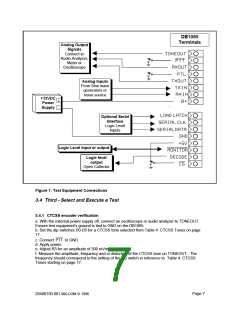
Terminals
Analog Output
Signals
Connect to
Audio Analyzer,
Meter or
Oscilloscope
Analog Inputs
From Sine wave
generators or
noise source
+12VDC
Power
Supply
+
-
Optional Serial
Interface
Logic Level
Inputs
Logic Level input or output
Logic level
output
Open Collector
Figure 1: Test Equipment Connections
3.4 Third - Select and Execute a Test
3.4.1 CTCSS encoder verification
a. With the external power supply off, connect an oscilloscope or audio analyzer to TONEOUT.
Ensure test equipment’s ground is tied to GND on the DB1065.
b. Set the dip switches D0-D5 for a CTCSS tone selected from Table 4: CTCSS Tones on page
17.
c. Connect PTT to GND.
d. Apply power.
e. Adjust R3 for an amplitude of 300 mVrms.
f. Measure the amplitude, frequency and or distortion of the CTCSS tone on TONEOUT. The
frequency should correspond to the setting of the dip switch in reference to Table 4: CTCSS
Tones starting on page 17.
Page 7
20480150.001 MX-COM ꢀ 1996

 CMLMICRO [ CML MICROCIRCUITS ]