GMSK Packet Data Modem and RF Transceiver
CMX990
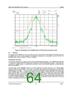
RBW
VBW
SWT
300 Hz
3 kHz
2.8 s
RF Att
Unit
30 dB
dBm
Ref Lvl
0 dBm
0
A
LIMIT CHECK : PASSED
-10
-20
-30
-40
1MA
-50
fcc210j
-60
-70
-80
-90
-100
Center 800.001496 MHz
5 kHz/
Span 50 kHz
Date:
31.MAR.2004 14:22:00
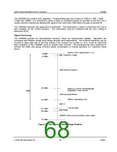
Figure 23 Modulation from CMX990 with 47 CFR 90.210 (J) emission mask
Receiver
6.3
The design of the CMX990 is such as to allow receiver requirements of the Mobitex standard to be met.
In addition the receiver is also capable of meeting the requirement of standards such as EN 300 113
although in this case an external 1st mixer is required.
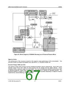
Architecture Overview
The receiver architecture is based on the classic superhetrodyne approach. The CMX990 provides the
1st mixer and IF stages with AGC followed by conversion to I/Q format baseband signals. These are then
converted to digital signals in sigma-delta converters, which also provide adjacent channel filtering,
before demodulation.
The first stage of the CMX990 receiver is a mixer intended to convert from RF to a 1st intermediate
frequency (IF) of around 45MHz. The mixer is an image reject type thus minimising the external filters
required before the mixer. The mixer would normally be preceded by input transmit/receive switch, low
noise amplifier and a filter. A typical noise figure for these stages is around 4dB with a recommended
gain of around 10dB. The noise figure of the mixers is very good for an image reject mixer (circa 13dB)
minimising pre-gain required to achieve a reasonable overall noise figure. It will be noted that the mixer
is a Gilbert cell type therefore requires a differential input. This can be achieved with a narrow-band LC
circuit or a balun transformer. The image reject network is selectable to give high side or low side
rejection depending on the frequency plan of RF and LO inputs.
ã 2004 CML Microsystems Plc
64
D/990/1

 CMLMICRO [ CML MICROCIRCUITS ]