GMSK Packet Data Modem and RF Transceiver
CMX990
along with RSSI/AGC algorithms. RSSI is available from a register. AGC can be controlled
automatically or manually. The baseband section also provides AFC measurement. Results are
available to the host and can be used (via Aux DAC 1) to control an external reference oscillator.
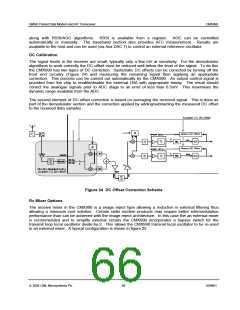
DC Calibration
The signal levels in the receiver are small, typically only a few mV at sensitivity. For the demodulator
algorithms to work correctly the DC offset must be reduced well below the level of the signal. To do this
the CMX990 has two types of DC correction. Systematic DC offsets can be corrected by turning off the
front end circuitry (Figure 24) and measuring the remaining signal then applying an appropriate
correction. This process can be carried out automatically by the CMX990. An output control signal is
provided from the chip to enable/disable the external LNA with appropriate timing. The result should
correct the analogue signals prior to ADC stage to an error of less than 0.5mV. This maximises the
dynamic range available from the ADC.
The second element of DC offset correction is based on averaging the received signal. This is done as
part of the demodulator section and the correction applied by adding/subtracting the measured DC offset
to the received data samples.
Figure 24 DC Offset Correction Scheme
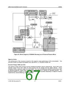
Rx Mixer Options
The receive mixer in the CMX990 is a image reject type allowing a reduction in external filtering thus
allowing a minimum cost solution. Certain radio modem products may require better intermodulation
performance than can be achieved with the image reject architecture. In this case the an external mixer
is recommended and to simplify external circuits the CMX990 incorporates a bypass switch for the
transmit loop local oscillator divide-by-2. This allows the CMX990 transmit local oscillator to be re-used
in an external mixer. A typical configuration is shown in figure 25.
ã 2004 CML Microsystems Plc
66
D/990/1

 CMLMICRO [ CML MICROCIRCUITS ]