GMSK Packet Data Modem and RF Transceiver
CMX990
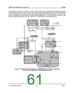
The image reject 1st mixer has been optimised to provide a minimum cost solution. The CMX990
provides the option to bypass the 1st mixer to achieve a lower overall power consumption and/or better
intermodulation performance using an external 1st mixer. Further details can be found below.
Following the 1st mixer the signal is passed off chip. A single ended output stage is used to ease
connection to IF filter components. The 1st IF can be in the range 44-46MHz with 45MHz being a typical
choice. Filtering is required at this point to achieve the Mobitex requirements and more stringent filtering
to meet EN 300 113. For Mobitex adjacent channel filtering can be met with digital filters at baseband,
however the blocking signal test at 84dB puts severe demands on the dynamic range of the baseband
sections so filtering at the IF is necessary. A 2-pole crystal filter is recommended. EN 300 113 has more
severe adjacent channel requirements so adjacent channel selectivity at the 1st IF is recommended. A 4-
pole crystal filter should be satisfactory. A summary of filter requirements can be found in Table 2. A
typical gain, noise figure and intermodulation partition is shown in Table 3 which assumes the filter
performance specified in Table 2.
Radio Modem Mode
(2 Pole Filter Recommended)
EN 300 113 Mode
(4 Pole Filter Recommended)
Frequency Offset
12.5 kHz
25 kHz
10dB
15dB
30dB
30dB
50 kHz
25dB
50dB
100 kHz
25dB
50dB
1 MHz to 10 MHz
Pass band (³ ±3.5 kHz)
40dB
3dB Typical
50dB
3dB Typical
Note: Attenuation relative to the pass band (with the exception of the pass band specification)
Table 2 IF Filter Requirements
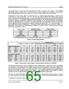
CMX990 Stages
1st Mixer IF Filter AGC/iq
Digital
Switch
Stage specifications:
LNA
BPF
Output
Filter
-4.01
13.0
6.5
Gain
NF
i/p IP
i/p cp
(dB)
(dB)
(dBm)
(dBm)
-1.0
1.0
40.0
30.0
15.0
2.9
0.0
-3.5
3.5
40.0
30.0
-4.5
4.5
40.0
30.0
63.0
8.1
-44.0
-54.0
0.0
0.0
99.0
99.0
0.0
0.0
99.0
99.0
-15.0
-2.0
Cumulative response:
preGain
Cum NF
i/p Te
Cum IP
i/p IM
(dB)
(dB)
(%)
(dBm)
(%)
0.0
8.4
4.4
-13.1
0.0
-1.0
7.4
20.4
-14.1
0.2
14.0
20.5
0.8
0.9
0.0
10.5
17.0
28.9
-2.6
6.5
11.1
3.8
-3.5
0.0
3.5
8.1
41.6
-44.0
24.0
66.5
0.0
0.0
97.5
0.0
66.5
0.0
0.0
99.0
0.0
75.9
Table 3 Typical Gain / Noise Figure / Intermodulation Partition for CMX990
The IF input stage goes into a gain controlled low noise amplifier stage. 45dB of AGC range is available
in 15dB steps. The output of the IF amplifiers passes to I/Q mixers which are fed a by a divide by 4
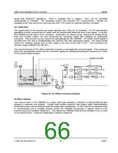
circuit from the IF local oscillator. The mixers include DC offset compensation. Baseband amplifiers are
then used to provide the correct input level to the ADC. The baseband amplifiers also include 55dB of
rejection at the ADC image frequency of 1.92MHz. This combined with at least 40dB of external
rejection from the IF filter provides adequate rejection to meet Mobitex requirements.
The ADC are sigma delta types providing high dynamic range and adjacent channel rejection. Internal
DC offset correction is provided to maximise the useable range. After the ADC demodulation is provided
1 Including loss of passive output matching
ã 2004 CML Microsystems Plc
65
D/990/1

 CMLMICRO [ CML MICROCIRCUITS ]