GMSK Packet Data Modem and RF Transceiver
CMX990
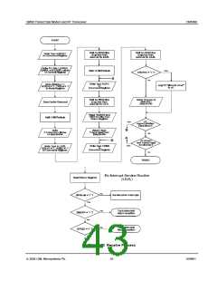
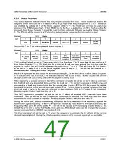
5.2.4 Status Registers
Two status registers indicate events that may require action by the host. Those marked as bold in the
diagrams below will cause bit 7 of Status1 (IRQ) to go high when they change from a 0 to 1. Interrupts
are enabled by setting bit 7 of the Mode register ($03) to '1', the IRQN pin will then be pulled low
whenever the IRQ bit goes high. If the IRQN line to the host is pulled low or if the host is polling for
interrupts then Status Register 1 should be read first then optionally followed by reading Status Register
2. The IRQ bit will be cleared to a '0' when the status register containing the interrupt(s) is read.
Status1
$01
Read
7
6
5
4
3
2
1
0
Bit:
Packet
Detect
IRQ
BFREE
IBEMPTY
DIBOVF
CRCFEC
DQRDY
MoBaN
See section 5.1.4.5 for a description of Status register 1.
Status2
$03
Read
7
6
5
4
3
2
1
0
Bit:
SPC
Aux ADC
PLL Lock
lost
Main PLL
in lock
Aux PLL
in lock
Tx PLL
in lock
Freq offset
error
IQ offset
complete
command conversion
complete complete
'PLL Lock lost' bit will be set to '1' whenever bits 4, 5 or 6 go from '1' to '0' since that bit was read as a '1'
from Status Register 2, i.e. PLL Lock lost bit is only set if lock has been gained, the host has read the
register to confirm this and that bit subsequently goes from a '1' to a '0'. This will cause bit 7 of Status1
to be set to '1' only if bit 3 of the Mode register ($03) is set to '1'. This bit will be cleared to ‘0’
immediately after reading the Status 2 register.
Bits 6 to 4 represent the lock status for the corresponding PLL at the time of the read of Status 2 register.
A '1' indicates the PLL is in lock, a '0' indicates that the PLL is not in lock. Buffer circuitry will prevent
changes in the lock status being lost while this register is being read.
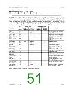
When operating a special command the 'SPC command complete' bit will be set to '1' when a command
has finished and any associated data can then be read out. The correct sequence to initiate a special
command is to load any required data into the special data registers $1B to $1E then issue the special
command by writing to the special command register $1A. Having issued a special command the host
must not read or write to the special command or data registers ($1A to $1E) until it has completed.
Reading register Status 2 will clear this bit to '0'.
'Aux ADC conversion complete' bit will be set to '1' when all enabled ADC channels have been
converted. This bit will not be set if continuous conversion is selected, the host may read the latest
conversion for each channel as required. Reading register Status 2 will clear this bit to '0'.
During Rx mode the CMX990 continuously compares the local reference clock frequency against the
received RF signal frequency. If these 2 frequencies deviate by more than the limit set by the host, the
frequency offset error bit will be set to '1'. This bit will be cleared to '0' by reading register Status 2. By
default the error limit is set so that this bit never gets set. This default value can be changed by issuing a
special command to the CMX990 (see section 5.2.4).
'IQ offset complete' bit will be set to '1' when the sequence to estimate the IQ offsets of the receive
channel has completed. During the offset acquisition sequence the received signal will be unreliable.
ã 2004 CML Microsystems Plc
47
D/990/1

 CMLMICRO [ CML MICROCIRCUITS ]