GMSK Packet Data Modem and RF Transceiver
CMX990
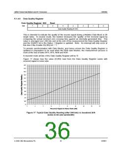
5.1.5.2 FEC
In transmit mode, during T7H, TSD and TDB, the modem generates a 4-bit Forward Error Correction
code for each coded byte. The FEC is defined by the following H matrix:
7______0
11101100
3___0
1000
0100
0010
0001
H = 11010011
10111010
01110101
Generation of the FEC consists of logically ANDing the byte to be transmitted with bits 7 to 0 of each row
of the H matrix. Even parity is generated for each of the 4 results and these 4 parity bits, in the positions
indicated by the last 4 columns of the H matrix, form the FEC code.
In checking the FEC, the received 12-bit word is logically ANDed with each row of the H matrix (earliest
bit received compared with the first column). Again even parity is generated for the 4 resulting words and
these parity bits form a 4-bit nibble. If this nibble is all zero then no errors have been detected. Other
results ‘point’ to the bit in error or indicate that uncorrectable errors have occurred.
This code can correct any single error that has occurred in each 12-bit (8 data + 4 FEC) section of the
message.
Example:
If the byte to be coded is ‘00101100’ then the FEC is derived as follows:
H matrix row:
1
2
3
4
A
B
11101100
00101100
00101100
1
11010011
00101100
00000000
0
10111010
00101100
00101000
0
01110101
00101100
00100100
0
A AND B
Even Parity:
where A is bits 7 - 0 of one row of the H matrix and B is the byte to be coded. The even parity
bits apply to the result of ‘A AND B’.
So the word formed will be: ‘00101100 1000’ sent left to right
When the same process is carried out on these 12 bits as above, using all 12 bits of each H
matrix row, the resulting 4 parity bits will be ‘0000’.
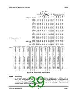
5.1.5.3 Interleaving
All the bits of transmitted Mobitex Data Blocks and Short Data Blocks are interleaved by the
modem to give protection against noise bursts and short fades. Interleaving is not performed
on any bits in the Mobitex Frame Head.
In the Mobitex Data Block case, considering the 240 bits to be numbered sequentially before
interleaving as 0 to 239 (‘0’ = bit 7 of byte 0, ‘11’ = bit 0 of FEC for byte 0, ... , ‘239’ = bit 0 of
FEC for byte 19 - see Figure 6), then they will be transmitted as shown in Figure 13. The
Mobitex Short Data Block is interleaved in a similar way; referring to Figure 13 consider bytes
4 and 5 as the CRC data and ignore bits 72 to 239 in the lower part of the diagram. i.e. the last
bit to be transmitted will be ‘71’.
The modem performs the inverse operation (de-interleaving) in receive mode on both Mobitex
Data Blocks and Short Data Blocks.
ã 2004 CML Microsystems Plc
38
D/990/1

 CMLMICRO [ CML MICROCIRCUITS ]