CS4365
3.2
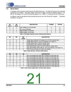
Mode Select
In hardware mode operation is determined by the Mode Select pins. The state of these pins are continually
scanned for any changes. These pins require connection to supply or ground as outlined in figure 8. For
M0, M1, M2 supply is VLC and for M3 and M4 supply is VLS. Tables 4 - 6 show the decode of these pins.
In software mode the operational mode and data format are set in the FM and DIF registers. “Parameter
Definitions” on page 45.
M1
M0
DESCRIPTION
FORMAT
FIGURE
(DIF1)
(DIF0)
Left Justified, up to 24-bit data
0
0
0
1
0
1
9
10
2
I S, up to 24-bit data
Right Justified, 16-bit Data
Right Justified, 24-bit Data
1
1
0
1
2
3
11
12
Table 4. PCM Digital Interface Format, Hardware Mode Options
M4
M3
M2
DESCRIPTION
(DEM)
Single-Speed without De-Emphasis (4 to 50 kHz sample rates)
Single-Speed with 44.1 kHz De-Emphasis; see Figure 18
Double-Speed (50 to 100 kHz sample rates)
0
0
0
0
1
1
1
0
0
1
1
0
0
1
0
1
0
1
0
1
X
Quad-Speed (100 to 200 kHz sample rates)
Auto Speed-Mode Detect (32 kHz to 200 kHz sample rates)
Auto Speed-Mode Detect with 44.1 kHz De-Emphasis; see Figure 18
DSD Processor Mode (see Table 6 for details)
Table 5. Mode Selection, Hardware Mode Options
M2
0
0
0
0
1
1
1
1
M1
0
0
1
1
0
0
1
1
M0
DESCRIPTION
64x oversampled DSD data with a 4x MCLK to DSD data rate
64x oversampled DSD data with a 6x MCLK to DSD data rate
64x oversampled DSD data with a 8x MCLK to DSD data rate
64x oversampled DSD data with a 12x MCLK to DSD data rate
128x oversampled DSD data with a 2x MCLK to DSD data rate
128x oversampled DSD data with a 3x MCLK to DSD data rate
128x oversampled DSD data with a 4x MCLK to DSD data rate
128x oversampled DSD data with a 6x MCLK to DSD data rate
0
1
0
1
0
1
0
1
Table 6. Direct Stream Digital (DSD), Hardware Mode Options
DS670PP1
21

 CIRRUS [ CIRRUS LOGIC ]