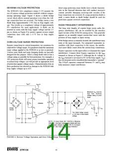
REVERSE-VOLTAGE PROTECTION
Most surge protection zener diodes have a diode character-
istic in the forward direction that will conduct excessive
current, possibly damaging receiving-side circuitry if the
loop connections are reversed. If a surge protection diode is
used, a series diode or diode bridge should be used for
protection against reversed connections.
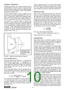
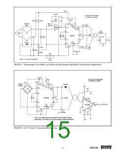
The XTR106’s low compliance rating (7.5V) permits the
use of various voltage protection methods without compro-
mising operating range. Figure 6 shows a diode bridge
circuit which allows normal operation even when the volt-
age connection lines are reversed. The bridge causes a two
diode drop (approximately 1.4V) loss in loop supply volt-
age. This results in a compliance voltage of approximately
9V—satisfactory for most applications. A diode can be
inserted in series with the loop supply voltage and the V+
pin as shown in Figure 8 to protect against reverse output
connection lines with only a 0.7V loss in loop supply
voltage.
RADIO FREQUENCY INTERFERENCE
The long wire lengths of current loops invite radio fre-
quency interference. RF can be rectified by the sensitive
input circuitry of the XTR106 causing errors. This generally
appears as an unstable output current that varies with the
position of loop supply or input wiring.
If the bridge sensor is remotely located, the interference may
enter at the input terminals. For integrated transmitter as-
semblies with short connection to the sensor, the interfer-
ence more likely comes from the current loop connections.
OVER-VOLTAGE SURGE PROTECTION
Remote connections to current transmitters can sometimes be
subjected to voltage surges. It is prudent to limit the maximum
surge voltage applied to the XTR106 to as low as practical.
Various zener diode and surge clamping diodes are specially
designed for this purpose. Select a clamp diode with as low a
voltage rating as possible for best protection. For example, a
36V protection diode will assure proper transmitter operation
at normal loop voltages, yet will provide an appropriate level
of protection against voltage surges. Characterization tests on
three production lots showed no damage to the XTR106 with
loop supply voltages up to 65V.
Bypass capacitors on the input reduce or eliminate this input
interference. Connect these bypass capacitors to the IRET
terminal as shown in Figure 6. Although the dc voltage at
the IRET terminal is not equal to 0V (at the loop supply, VPS)
this circuit point can be considered the transmitter’s “ground.”
The 0.01µF capacitor connected between V+ and IO may
help minimize output interference.
VREF
5
VREF2.5
14
13
5
Maximum VPS must be
less than minimum
voltage rating of zener
diode.
+
VIN
10
V+
4
5V
RG
0.01µF
9
8
1N4148
Diodes
B
E
Q1
(1)
RB
RG
+
–
D1
XTR106
3
2
RG
VI–N
Bridge
Sensor
RL
VPS
IO
The diode bridge causes
a 1.4V loss in loop supply
voltage.
7
IRET
6
0.01µF
0.01µF
NOTE: (1) Zener Diode 36V: 1N4753A or Motorola
P6KE39A. Use lower voltage zener diodes with loop
power supply voltages less than 30V for increased
protection. See “Over-Voltage Surge Protection.”
FIGURE 6. Reverse Voltage Operation and Over-Voltage Surge Protection.
®
14
XTR106

 BB [ BURR-BROWN CORPORATION ]