The transfer function for the complete current transmitter is:
APPLICATIONS INFORMATION
IO = 4mA + VIN • (40/RG)
VIN in Volts, RG in Ohms
(1)
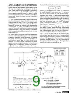
Figure 1 shows the basic connection diagram for the XTR106.
The loop power supply, VPS, provides power for all cir-
cuitry. Output loop current is measured as a voltage across
the series load resistor, RL. A 0.01µF to 0.03µF supply
bypass capacitor connected between V+ and IO is recom-
mended. For applications where fault and/or overload con-
ditions might saturate the inputs, a 0.03µF capacitor is
recommended.
where VIN is the differential input voltage. As evident from
the transfer function, if no RG is used (RG = ∞), the gain is
zero and the output is simply the XTR106’s zero current.
A negative input voltage, VIN, will cause the output current
to be less than 4mA. Increasingly negative VIN will cause the
output current to limit at approximately 1.6mA. If current is
being sourced from the reference and/or VREG, the current
limit value may increase. Refer to the Typical Performance
Curves, “Under-Scale Current vs IREF + IREG” and “Under-
Scale Current vs Temperature.”
A 2.5V or 5V reference is available to excite a bridge sensor.
For 5V excitation, pin 14 (VREF5) should be connected to the
bridge as shown in Figure 1. For 2.5V excitation, connect
pin 13 (VREF2.5) to pin 14 as shown in Figure 3b. The output
terminals of the bridge are connected to the instrumentation
amplifier inputs, VI+N and VI–N. A 0.01µF capacitor is shown
connected between the inputs and is recommended for high
impedance bridges (> 10kΩ). The resistor RG sets the gain
of the instrumentation amplifier as required by the full-scale
bridge voltage, VFS.
Increasingly positive input voltage (greater than the full-
scale input, VFS) will produce increasing output current
according to the transfer function, up to the output current
limit of approximately 28mA. Refer to the Typical Perfor-
mance Curve, “Over-Scale Current vs Temperature.”
The IRET pin is the return path for all current from the
references and VREG. IRET also serves as a local ground and
is the reference point for VREG and the on-board voltage
references. The IRET pin allows any current used in external
circuitry to be sensed by the XTR106 and to be included in
the output current without causing error. The input voltage
range of the XTR106 is referred to this pin.
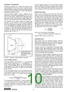
Lin Polarity and RLIN provide second-order linearization
correction to the bridge, achieving up to a 20:1 improvement
in linearity. Connections to Lin Polarity (pin 12) determine
the polarity of nonlinearity correction and should be con-
nected either to IRET or VREG. Lin Polarity should be con-
nected to VREG even if linearity correction is not desired.
RLIN is chosen according to the equation in Figure 1 and is
dependent on KLIN (linearization constant) and the bridge’s
nonlinearity relative to VFS (see “Linearization” section).
Possible choices for Q1 (see text).
VREG
For 2.5V excitation, connect
pin 13 to pin 14
TYPE
PACKAGE
VREF
5
VREF2.5
(3)
RLIN
2N4922
TIP29C
TIP31C
TO-225
TO-220
TO-220
14
13
7.5V to 36V
11
5
1
+
RLIN
VIN
10
VREG
V+
IO
CIN
0.01µF(2)
4
5V
RG
4-20 mA
R(15)
COUT
0.01µF
9
8
R2(5)
RG(4)
B
E
Q1
RB
+
–
XTR106
VO
+
3
Bridge
Sensor
RG
VI–N
RL
VPS
–
Lin(1)
Polarity
IO
7
2
IRET
12
6
40
RG
IO = 4mA + VIN • (
)
(1)
VREG
or
1 + 2B
1 – 2B
NOTES:
(VFS in V)
(4)
RG = (VFS/400µA) •
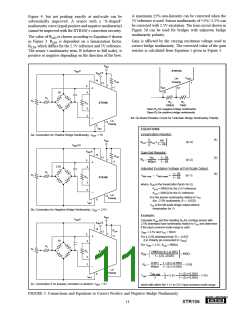
(1) Connect Lin Polarity (pin 12) to IRET (pin 6) to correct for positive
bridge nonlinearity or connect to VREG (pin 1) for negative bridge
nonlinearity. The RLIN pin and Lin Polarity pin must be connected to
VREG if linearity correction is not desired. Refer to “Linearization”
section and Figure 3.
where KLIN = 9.905kΩ for 2.5V reference
KLIN = 6.645kΩ for 5V reference
B is the bridge nonlinearity relative to VFS
VFS is the full-scale input voltage
(2) Recommended for bridge impedances > 10kΩ
4B
(5) R1 and R2 form bridge trim circuit to compensate for the initial
accuracy of the bridge. See “Bridge Balance” text.
(KLIN in Ω)
( 3)
RLIN = KLIN
•
1 – 2B
FIGURE 1. Basic Bridge Measurement Circuit with Linearization.
9
®
XTR106

 BB [ BURR-BROWN CORPORATION ]