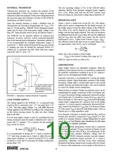
A maximum ±5% non-linearity can be corrected when the
5V reference is used. Sensor nonlinearity of +5%/–2.5% can
be corrected with 2.5V excitation. The trim circuit shown in
Figure 3d can be used for bridges with unknown bridge
nonlinearity polarity.
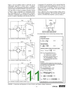
Figure 4, but not peaking exactly at mid-scale can be
substantially improved. A sensor with a “S-shaped”
nonlinearity curve (equal positive and negative nonlinearity)
cannot be improved with the XTR106’s correction circuitry.
The value of RLIN is chosen according to Equation 4 shown
in Figure 3. RLIN is dependent on a linearization factor,
KLIN, which differs for the 2.5V reference and 5V reference.
The sensor’s nonlinearity term, B (relative to full scale), is
positive or negative depending on the direction of the bow.
Gain is affected by the varying excitation voltage used to
correct bridge nonlinearity. The corrected value of the gain
resistor is calculated from Equation 5 given in Figure 3.
VREG
XTR106
VREF5
VREF2.5
VREG
Lin
Polarity
14
13
RLIN
11
1
1
5
IRET
6
12
+
–
5V
4
R1
R2
RX
100kΩ
RY
15kΩ
+
–
RG
3
XTR106
Open RX for negative bridge nonlinearity
Open RY for positive bridge nonlinearity
2
3d. On-Board Resistor Circuit for Unknown Bridge Nonlinearity Polarity
Lin
Polarity
12
6
IRET
EQUATIONS
Linearization Resistor:
3a. Connection for Positive Bridge Nonlinearity, VREF = 5V
(4)
VREG
4B
(in Ω)
(in Ω)
RLIN
= KLIN •
1– 2B
VREF2.5
V
5
REF5
Gain-Set Resistor:
14
RLIN
11
13
VFS
(5)
(6)
1+ 2B
RG
=
•
1
400µA
1– 2B
+
2.5V
+
4
Adjusted Excitation Voltage at Full-Scale Output:
R1
1+ 2B
R2
VREF (Adj)
=
VREF (Initial)
•
(in V)
–
RG
3
XTR106
1– 2B
where, KLIN is the linearization factor (in Ω)
K
LIN = 9905Ω for the 2.5V reference
LIN = 6645Ω for the 5V reference
2
–
K
Lin
Polarity
12
B is the sensor nonlinearity relative to VFS
(for –2.5% nonlinearity, B = –0.025)
6
IRET
VFS is the full-scale bridge output without
linearization (in V)
3b. Connection for Negative Bridge Nonlinearity, VREF = 2.5V
Example:
VREG
VREF5
Calculate RLIN and the resulting RG for a bridge sensor with
2.5% downward bow nonlinearity relative to VFS and determine
if the input common-mode range is valid.
VREF2.5
14
13
RLIN
11
VREF = 2.5V and VFS = 50mV
1
5
+
–
For a 2.5% downward bow, B = –0.025
(Lin Polarity pin connected to VREG
)
5V
4
For VREF = 2.5V, KLIN = 9905Ω
R1
R2
+
–
RG
3
XTR106
(9905Ω) (4) (–0.025)
RLIN
=
=
=
= 943Ω
1– (2) (–0.025)
0.05V 1+ (2) (–0.025)
2
RG
•
= 113Ω
400µA 1 – (2) (–0.025)
Lin
Polarity
12
VREF (Adj)
1
2
1+ (2) (–0.025)
6
VCM
=
• 2.5V •
= 1.13V
IRET
2
1– (2) (–0.025)
3c. Connection if no linearity correction is desired, VREF = 5V
which falls within the 1.1V to 3.5V input common-mode range.
FIGURE 3. Connections and Equations to Correct Positive and Negative Bridge Nonlinearity.
11
®
XTR106

 BB [ BURR-BROWN CORPORATION ]