TSC2005
www.ti.com
SBAS379–DECEMBER 2006
OVERVIEW (continued)
INTERNAL TEMPERATURE SENSOR
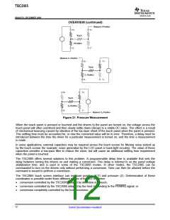
In some applications, such as battery recharging, a measurement of ambient temperature is required. The
temperature measurement technique used in the TSC2005 relies on the characteristics of a semiconductor
junction operating at a fixed current level. The forward diode voltage (VBE) has a well-defined characteristic
versus temperature. The ambient temperature can be predicted in applications by knowing the +25°C value of
the VBE voltage and then monitoring the delta of that voltage as the temperature changes.
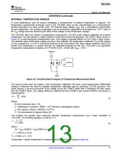
The TSC2005 offers two modes of temperature measurement. The first mode requires calibration at a known
temperature, but only requires a single reading to predict the ambient temperature. The TEMP1 diode, shown in
Figure 22, is used during this measurement cycle. This voltage is typically 580mV at +25°C with a 10µA current.
The absolute value of this diode voltage can vary a few millivolts; the temperature coefficient (TC) of this voltage
is very consistent at –2.1mV/°C. During the final test of the end product, the diode voltage would be stored at a
known room temperature, in system memory, for calibration purposes by the user. The result is an equivalent
temperature measurement resolution of 0.3°C/LSB (1LSB = 610µV with VREF = 2.5V).
SNSVDD
+IN
Converter
-IN
AGND
Figure 22. Functional Block Diagram of Temperature Measurement Mode
The second mode does not require a test temperature calibration, but uses a two-measurement (differential)
method to eliminate the need for absolute temperature calibration and for achieving 2°C/LSB accuracy. This
mode requires a second conversion of the voltage across the TEMP2 diode with a resistance 80 times larger
than the TEMP1 diode. The voltage difference between the first (TEMP1) and second (TEMP2) conversion is
represented by:
kT
q
DV +
@ ln(N)
(3)
Where:
N is the resistance ratio = 80,
k = Boltzmann's constant (1.38054 × 10⁻²³ electrons volts/degrees Kelvin),
q = the electron charge (1.602189 × 10⁻¹⁹°C),
T = the temperature in degrees Kelvin (K).
This method can provide much improved absolute temperature measurement, but a lower resolution of
1.6°C/LSB. The resulting equation to solve for T is:
q @ DV
k @ ln(N)
T +
(4)
Where:
∆V = VBE (TEMP2) – VBE(TEMP1) (in mV)
T = 2.648 •∆ V (in K)
°C = 2.648 • ∆ V – 273
Temperature 1 and/or temperature 2 measurements have the same timing as Figure 38.
13
Submit Documentation Feedback

 BB [ BURR-BROWN CORPORATION ]