TSC2005
www.ti.com
SBAS379–DECEMBER 2006
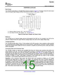
OVERVIEW (continued)
TOUCH SCREEN OPERATION
A resistive touch screen operates by applying a voltage across a resistor network and measuring the change in
resistance at a given point on the matrix where the screen is touched by an input (stylus, pen, or finger). The
change in the resistance ratio marks the location on the touch screen.
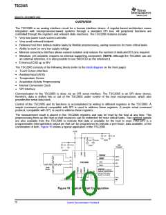
The TSC2005 supports the resistive 4-wire configurations, as shown in Figure 20. The circuit determines
location in two coordinate pair dimensions, although a third dimension can be added for measuring pressure.
4-WIRE TOUCH SCREEN COORDINATE PAIR MEASUREMENT
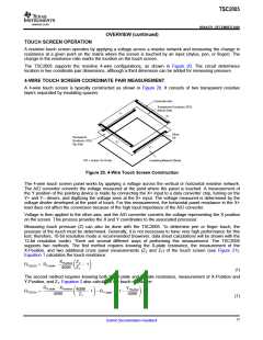
A 4-wire touch screen is typically constructed as shown in Figure 20. It consists of two transparent resistive
layers separated by insulating spacers.
Conductive Bar
Transparent Conductor (ITO)
Bottom Side
Y+
X+
Silver
Transparent
Conductor (ITO)
Top Side
Ink
X-
Y-
Insulating Material (Glass)
ITO = Indium Tin Oxide
Figure 20. 4-Wire Touch Screen Construction
The 4-wire touch screen panel works by applying a voltage across the vertical or horizontal resistive network.
The A/D converter converts the voltage measured at the point where the panel is touched. A measurement of
the Y position of the pointing device is made by connecting the X+ input to a data converter chip, turning on the
Y+ and Y– drivers, and digitizing the voltage seen at the X+ input. The voltage measured is determined by the
voltage divider developed at the point of touch. For this measurement, the horizontal panel resistance in the X+
lead does not affect the conversion because of the high input impedance of the A/D converter.
Voltage is then applied to the other axis, and the A/D converter converts the voltage representing the X position
on the screen. This process provides the X and Y coordinates to the associated processor.
Measuring touch pressure (Z) can also be done with the TSC2005. To determine pen or finger touch, the
pressure of the touch must be determined. Generally, it is not necessary to have very high performance for this
test; therefore, 10-bit resolution mode is recommended (however, data sheet calculations will be shown with the
12-bit resolution mode). There are several different ways of performing this measurement. The TSC2005
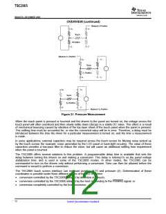
supports two methods. The first method requires knowing the X-plate resistance, the measurement of the
X-Position, and two additional cross panel measurements (Z2 and Z1) of the touch screen (see Figure 21).
Equation 1 calculates the touch resistance:
XPostition Z2
ǒ Ǔ
RTOUCH + RX−plate
@
* 1
4096
Z1
(1)
The second method requires knowing both the X-plate and Y-plate resistance, measurement of X-Position and
Y-Position, and Z1. Equation 2 also calculates the touch resistance:
RX−plate @ XPostition
YPosition
4096
4096
Z1
ǒ Ǔ ǒ1* Ǔ
RTOUCH
+
*1 *RY−plate @
4096
(1)
11
Submit Documentation Feedback

 BB [ BURR-BROWN CORPORATION ]