PCM3793A
PCM3794A
www.ti.com
SLAS529A–JANUARY 2007–REVISED FEBRUARY 2007
DESCRIPTION OF OPERATION
System Clock Input
The PCM3793A/94A can accept clocks of various frequencies without a PLL. They are used for clocking the
digital filters and automatic level control and delta-sigma modulators and are classified as common-audio and
application-specific clocks. Table 2 shows frequencies of the common-audio clock and application-specific clock.
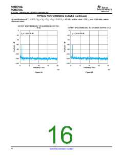
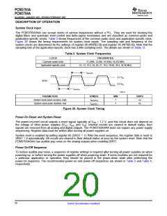
Figure 26 shows the timing requirements for system clock inputs. The sampling rate and frequency of the
system clocks are determined by the settings of register 86 (MSR[2:0]) and register 85 (NPR[5:0]). Note that the
sampling rate of the application-specific clock has a little sampling error. The details are shown in Table 12.
Table 2. System Clock Frequencies
CLOCK
FREQUENCIES
Common-audio clock
Application-specific clock
11.2896, 12.288, 16.9344, 18.432 MHz
12, 13, 13.5, 24, 26, 27, 19.2, 19.68, 38.4, 39.36 MHz
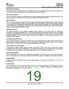
tw(SCKH)
0.7 VIO
SCKI
0.3 VIO
tw(SCKL)
T0005-12
PARAMETERS
SYMBOL
tw(SCKH)
tw(SCKL)
MIN
7
UNITS
ns
System-clock pulse duration, high
System-clock pulse duration, low
7
ns
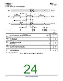
Figure 26. System Clock Timing
Power-On Reset and System Reset
The power-on-reset circuit outputs a reset signal, typically at VDD = 1.2 V, and this circuit does not depend on
the voltage of other power supplies (VCC, VPA, and VIO). Internal circuits are cleared to default status, then
signals are removed from all analog and digital outputs. The PCM3793A/94A does not require any power supply
sequencing. Register data must be written after turning all power supplies on.
System reset is enabled by setting register 85 (SRST = 1). After the reset sequence, the register data is reset to
SRST = 0 automatically. All circuits are cleared to their default status at once by the system reset. Note that the
PCM3793A/94A has audible pop noise on the analog outputs when enabling SRST.
Power On/Off Sequence
To reduce audible pop noise, a sequence of register settings is required after turning all power supplies on when
powering up, or before turning the power supplies off when powering down. If some modules are not required for
a particular application or operation, they should be placed in the power-down state after performing the
power-on sequence. The recommended power-on and power-off sequences are shown in Table 3 and Table 4,
respectively.
20
Submit Documentation Feedback

 BB [ BURR-BROWN CORPORATION ]