PCM3793A
PCM3794A
www.ti.com
SLAS529A–JANUARY 2007–REVISED FEBRUARY 2007
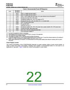
Table 4. Recommended Power-Off Sequence
REGISTER
SETTINGS
STEP
NOTE
1
2
447Fh
457Fh
5132h
5811h
49FCh
5200h
5A00h
4A00h
–
DAC L-ch digital soft-mute enable(1)
DAC R-ch digital soft-mute enable(1)
ADC L-ch/R-ch digital soft-mute enable, ADC audio interface format (left-justified)(2)
3
4
Analog mixer input (SW2, SW5) select
(3)(4)
5
Headphone amplifier (HPL, HPR, HPC) power up
6
Analog front end (ADL, ADR, D2S, MCB, PG1, 2, 5, 6) power down
PG1, PG2 gain control (0 dB)
7
8
VCOM power down
(5)
9
Wait time (750 ms)
10
11
12
13
49E0h
4800h
4900h
–
Headphone amplifier (HPL, HPR, HPC) power down, speaker amplifier (SPL, SPR) power down
Analog mixer (MXL, MXR) power down
DAC (DAL, DAR) and analog bias power down
Turn off all power supplies.(6)
(1) Any level is acceptable for volume or attenuation.
(2) Audio interface format should be set to match the DSP or decoder in the application.
(3) The PCM3794A has no speaker amplifier.
(4) The headphone amplifier must be operating during the power-off sequence.
(5) PCM3793A requires time for VCOM to reach the ground level from the common level. The wait time allowed depends on the settings of
register 125 PTM[1:0], RES[4:0]. The default setting is 750 ms for VCOM = 4.7 µF.
(6) Power supply sequencing is not required. It is recommended to turn off all power supplies after setting the registers with the system
clock input.
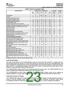
Power-Supply Current
The current consumption of the PCM3793A/94A depends on power up/down status of each circuit module. In
order to reduce the power consumption, disabling each module is recommended when it is not used in an
application or operation. Table 5 shows the current consumption in some states.
22
Submit Documentation Feedback

 BB [ BURR-BROWN CORPORATION ]