ꢀ ꢁꢂ ꢃ ꢄꢅ ꢆ
www.ti.com
SLES100 − DECEMBER 2003
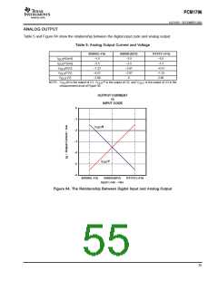
ANALOG OUTPUT
Table 5 and Figure 64 show the relationship between the digital input code and analog output.
Table 5. Analog Output Current and Voltage
800000 (–FS)
–1.5
000000 (BPZ)
7FFFFF (+FS)
–5.5
I
N [mA]
P [mA]
–3.5
–3.5
–2.87
–2.87
0
OUT
I
–5.5
–1.5
OUT
V
N [V]
P [V]
–1.23
–4.51
OUT
V
–4.51
–1.23
OUT
V
[V]
–2.98
2.98
OUT
NOTE: V
N is the output of U1, V
measurementcircuit of Figure 36.
P is the output of U2, and V
OUT
is the output of U3 in the
OUT
OUT
OUTPUT CURRENT
vs
INPUT CODE
0
−1
−2
−3
−4
−5
−6
I
N
OUT
I
P
OUT
800000(−FS)
000000(BPZ)
7FFFFF(+FS)
Input Code − Hex
Figure 64. The Relationship Between Digital Input and Analog Output
55

 BB [ BURR-BROWN CORPORATION ]