ꢀ ꢁꢂ ꢃ ꢄꢅ ꢆ
www.ti.com
SLES100 − DECEMBER 2003
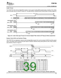
Audio Format
The PCM1796 in the external digital filter interface mode supports right-justified audio formats including 16-bit, 20-bit,
and 24-bit audio data, as shown in Figure 40. The audio format is selected by the FMT[2:0] bits of control register18.
1/4 f or 1/8 f
S
S
WDCK
BCK
Audio Data Word = 16-Bit
DATA,
DATAL, DATAR
15 16
1
2
3
4
8
5
9
6
7
8
9
10 11 12 13 14 15 16
LSB
MSB
Audio Data Word = 20-Bit
DATA,
19 20
1
5
2
6
3
4
8
5
9
6
7
10 11 12 13 14 15 16 17 18 19 20
LSB
DATAL, DATAR
MSB
Audio Data Word = 24-Bit
DATA,
23 24
1
2
3
4
7
10 11 12 13 14 15 16 17 18 19 20 21 22 23 24
LSB
DATAL, DATAR
MSB
Figure 40. Audio Data Input Format for External Digital Filter (Internal DF Bypass Mode) Application
System Clock (SCK) and Interface Timing
The PCM1796 in an application using an external digital filter requires the synchronization of WDCK and the system
clock. The system clock is phase-free with respect to WDCK. Interface timing among WDCK, BCK, DATA, DATAL,
and DATAR is shown in Figure 41.
1.4 V
1.4 V
1.4 V
WDCK
BCK
t
t
t
(LB)
(BCH)
(BCL)
t
t
(BCY)
(BL)
DATA
DATAL
DATAR
t
t
(DS)
(DH)
PARAMETER
MIN
20
7
MAX UNITS
t
t
t
t
t
t
t
BCK pulse cycle time
ns
ns
ns
ns
ns
ns
ns
(BCY)
(BCL)
(BCH)
(BL)
BCK pulse duration, LOW
BCK pulse duration, HIGH
7
BCK rising edge to WDCK falling edge
WDCK falling edge to BCK rising edge
DATA, DATAL, DATAR setup time
DATA, DATAL, DATAR hold time
5
5
(LB)
5
(DS)
5
(DH)
Figure 41. Audio Interface Timing for External Digital Filter (Internal DF Bypass Mode) Application
39

 BB [ BURR-BROWN CORPORATION ]