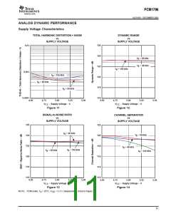
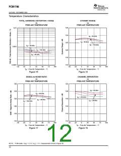
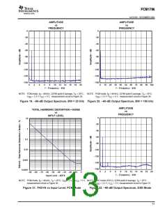
ꢀ
ꢁ
ꢂ
ꢃ
ꢄ
ꢅ
ꢆ
www.ti.com
SLES100 − DECEMBER 2003
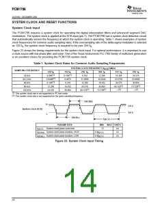
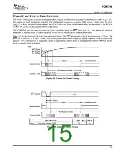
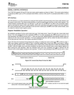
Power-On and External Reset Functions
The PCM1796 includes a power-on reset function. Figure 24 shows the operation of this function. With V
> 2 V,
DD
the power-on reset function is enabled. The initialization sequence requires 1024 system clocks from the time
> 2 V. After the initialization period, the PCM1796 is set to its default reset state, as described in the MODE
V
DD
CONTROL REGISTERS section of this data sheet.
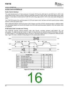
The PCM1796 also includes an external reset capability using the RST input (pin 14). This allows an external
controller or master reset circuit to force the PCM1796 to initialize to its default reset state.
Figure 25 shows the external reset operation and timing. The RST pin is set to logic 0 for a minimum of 20 ns. The
RST pin is then set to a logic 1 state, thus starting the initialization sequence, which requires 1024 system clock
periods. The external reset is especially useful in applications where there is a delay between the PCM1796 power
up and system clock activation.
V
DD
2.4 V (Max)
2.0 V (Typ)
1.6 V (Min)
Reset
Reset Removal
Internal Reset
System Clock
1024 System Clocks
Figure 24. Power-On Reset Timing
RST (Pin 14)
1.4 V
t
(RST)
Reset
Reset Removal
Internal Reset
System Clock
1024 System Clocks
PARAMETERS
Reset pulse duration, LOW
MIN
MAX UNITS
t
20
ns
(RST)
Figure 25. External Reset Timing
15

 BB [ BURR-BROWN CORPORATION ]