PCM1753
PCM1754
PCM1755
SLES092A – OCTOBER 2003 – REVISED AUGUST 2004
www.ti.com
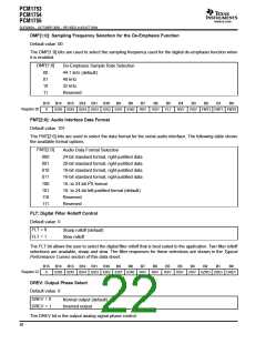
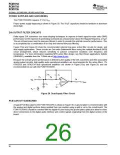
POWER SUPPLIES AND GROUNDING
The PCM1753/54/55 requires 5 V for V
.
CC
Proper power supply bypassing is shown in Figure 28. The 10-µF capacitors should be tantalum or aluminum
electrolytic.
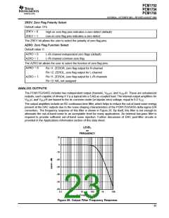
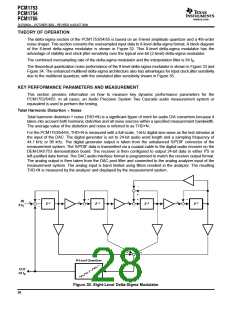
D/A OUTPUT FILTER CIRCUITS
Delta-sigma D/A converters use noise-shaping techniques to improve in-band signal-to-noise ratio (SNR)
performance at the expense of generating increased out-of-band noise above the Nyquist frequency, or f /2.
S
The out-of-band noise must be low-pass filtered in order to provide the optimal converter performance. This
is accomplished by a combination of on-chip and external low-pass filtering.
Figure 27(a) and Figure 29 show the recommended external low-pass active filter circuits for single- and
dual-supply applications. These circuits are 2nd-order Butterworth filters using the multiple feedback (MFB)
circuit arrangement, which reduces sensitivity to passive component variations over frequency and
temperature. For more information regarding MFB active filter design, see Burr-Brown applications bulletin
(SBAA055), available from the TI Web site at http://www.ti.com.
Because the overall system performance is defined by the quality of the D/A converters and their associated
analog output circuitry, high-quality audio operational amplifiers are recommended for the active filters. TI’s
OPA2353 and OPA2134 dual operational amplifiers are shown in Figure 27(a) and Figure 29, and are
recommended for use with the PCM1753/54/55.
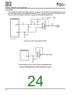
R
2
C
1
R
1
R
3
2
R
4
–
V
IN
1
OPA2134
V
OUT
3
C
2
+
R2
R1
AV [ *
Figure 29. Dual-Supply Filter Circuit
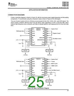
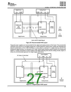
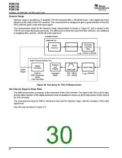
PCB LAYOUT GUIDELINES
A typical PCB floor plan for the PCM1753/54/55 is shown in Figure 30. A ground plane is recommended, with
the analog and digital sections being isolated from one another using a split or cut in the circuit board. The
PCM1753/54/55 should be oriented with the digital I/O pins facing the ground plane split/cut to allow for short,
direct connections to the digital audio interface and control signals originating from the digital section of the
board.
26

 BB [ BURR-BROWN CORPORATION ]