PCM1753
PCM1754
PCM1755
www.ti.com
SLES092A – OCTOBER 2003 – REVISED AUGUST 2004
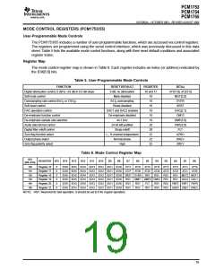
MODE CONTROL REGISTERS (PCM1753/55)
User-Programmable Mode Controls
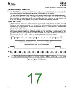
The PCM1753/55 includes a number of user programmable functions, which are accessed via control registers.
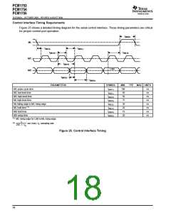
The registers are programmed using the serial control interface, which was previously discussed in this data
sheet. Table 5 lists the available mode control functions, along with their reset default conditions and associated
register index.
Register Map
The mode control register map is shown in Table 6. Each register includes an index (or address) indicated by
the IDX[6:0] bits.
Table 5. User-Programmable Mode Controls
FUNCTION
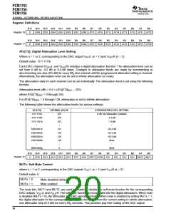
Digital attenuation control, 0 dB to –63 dB in 0.5-dB steps
Soft mute control
RESET DEFAULT
0 dB, no attenuation
Mute disabled
REGISTER
BIT(s)
AT1[7:0], AT2[7:0]
MUT[2:0]
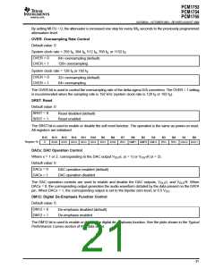
OVER
16 and 17
18
Oversampling rate control (64 f or 128 f )
64 f oversampling
18
S
S
S
Soft reset control
Reset disabled
DAC1 and DAC2 enabled
De-emphasis disabled
44.1 kHz
18
SRST
DAC operation control
De-emphasis function control
19
DAC[2:1]
DM12
19
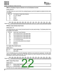
De-emphasis sample rate selection
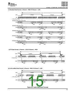
Audio data format control
Digital filter rolloff control
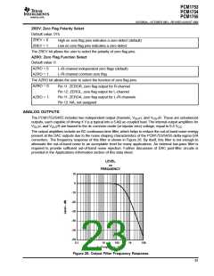
Zero flag function select
Output phase select
19
DMF[1:0]
FMT[2:0]
FLT
24-bit left-justified
Sharp rolloff
20
20
L-, R-channel independent
Normal phase
22
AZRO
22
DREV
Zero flag polarity select
High
22
ZREV
Table 6. Mode Control Register Map
IDX
(B8–B14)
REGISTER B15
B14
B13
B12
B11
B10
B9
B8
B7
B6
B5
B4
B3
B2
B1
B0
10h
Register 16
Register 17
Register 18
Register 19
Register 20
Register 22
0
0
0
0
0
0
IDX6 IDX5 IDX4 IDX3 IDX2 IDX1 IDX0
IDX6 IDX5 IDX4 IDX3 IDX2 IDX1 IDX0
AT17
AT27
AT16
AT26
AT15
AT25
RSV
AT14 AT13
AT24 AT23
AT12
AT22
RSV
RSV
AT11
AT21
AT10
AT20
11h
12h
IDX6 IDX5 IDX4 IDX3 IDX2 IDX1 IDX0 SRST OVER
RSV
RSV
MUT2 MUT1
DAC2 DAC1
13h
IDX6 IDX5 IDX4 IDX3 IDX2 IDX1 IDX0
IDX6 IDX5 IDX4 IDX3 IDX2 IDX1 IDX0
IDX6 IDX5 IDX4 IDX3 IDX2 IDX1 IDX0
RSV
RSV
RSV
DMF1 DMF0 DM12 RSV
14h
RSV
RSV
FLT
RSV
RSV
RSV FMT2 FMT1 FMT0
RSV AZRO ZREV DREV
16h
:
RSV
NOTE RSV: Reserved for test operation. It should be set to 0 for regular operation.
19

 BB [ BURR-BROWN CORPORATION ]