PCM1753
PCM1754
PCM1755
SLES092A – OCTOBER 2003 – REVISED AUGUST 2004
www.ti.com
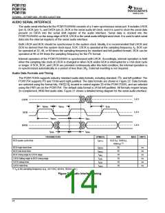
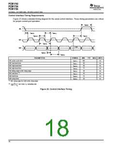
Control Interface Timing Requirements
Figure 25 shows a detailed timing diagram for the serial control interface. These timing parameters are critical
for proper control port operation.
t
(MHH)
ML
t
t
(MCL)
(MLS)
t
t
(MLH)
(MCH)
MC
MD
t
(MCY)
LSB
t
(MDS)
t
(MDH)
PARAMETERS
SYMBOL
MIN
100
50
TYP
MAX UNITS
MC pulse cycle time
MC low-level time
MC high-level time
ML high-level time
t
ns
ns
ns
ns
ns
ns
ns
ns
(MCY)
t
(MCL)
(MCH)
(MHH)
t
t
50
(2)
ML falling edge to MC rising edge
t
t
20
20
15
20
(MLS)
(MLH)
(MDH)
(MDS)
(1)
ML hold time
MD hold time
MD setup time
t
t
(1)
MC rising edge for LSB to ML rising edge.
3
(2)
sec (min); f : sampling rate
S
256 f
S
Figure 25. Control Interface Timing
18

 BB [ BURR-BROWN CORPORATION ]