4500Vrms for one second. This is to guarantee the isolation
amplifier will survive a 3750V transient voltage. The barrier
leakage current test limit is 5µA. Pins 1-4 are shorted
together and pins 5-8 are shorted together during the test.
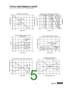
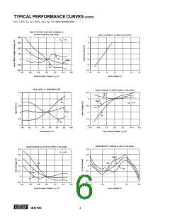
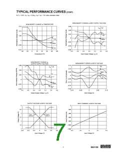
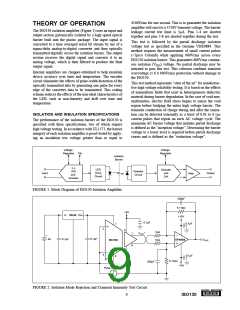
THEORY OF OPERATION
The ISO130 isolation amplifier (Figure 1) uses an input and
output section galvanically isolated by a high speed optical
barrier built into the plastic package. The input signal is
converted to a time averaged serial bit stream by use of a
sigma-delta analog-to-digital converter and then optically
transmitted digitally across the isolation barrier. The output
section receives the digital signal and converts it to an
analog voltage, which is then filtered to produce the final
output signal.
This test is followed by the partial discharge isolation
voltage test as specified in the German VDE0884. This
method requires the measurement of small current pulses
(<5pico Colomb) while applying 960Vrms across every
ISO130 isolation barrier. This guarantees 600Vrms continu-
ous isolation (VISO) voltage. No partial discharge may be
initiated to pass this test. This criterion confirms transient
overvoltage (1.6 x 600Vrms) protection without damage to
the ISO130.
Internal amplifiers are chopper-stabilized to help maintain
device accuracy over time and temperature. The encoder
circuit eliminates the effects of pulse-width distortion of the
optically transmitted data by generating one pulse for every
edge of the converter data to be transmitted. This coding
scheme reduces the effects of the non-ideal characteristics of
the LED, such as non-linearity and drift over time and
temperature.
This test method represents “state of the art” for nondestruc-
tive high voltage reliability testing. It is based on the effects
of nonuniform fields that exist in heterogeneous dielectric
material during barrier degradation. In the case of void non-
uniformities, electric field stress begins to ionize the void
region before bridging the entire high voltage barrier. The
transient conduction of charge during and after the ioniza-
tion can be detected externally as a burst of 0.01 to 0.1µs
current pulses that repeat on each AC voltage cycle. The
minimum AC barrier voltage that initiates partial discharge
is defined as the “inception voltage”. Decreasing the barrier
voltage to a lower level is required before partial discharge
ceases and is defined as the “extinction voltage”.
ISOLATION AND INSULATION SPECIFICATIONS
The performance of the isolation barrier of the ISO130 is
specified with three specifications, two of which require
high voltage testing. In accordance with UL1577, the barrier
integrity of each isolation amplifier is proof-tested by apply-
ing an insulation test voltage greater than or equal to
Voltage
Voltage
Regulator
Regulator
Clk
Isolation
Barrier
Σ ∆
A/D
and
LED
Drive
Circuit
Decoder
Detector
CIrcuit
and
D/A
Input
Output
Filter
Encoder
FIGURE 1. Block Diagram of ISO130 Isolation Amplifier.
330pF
5.11kΩ
+5V
In 78L05 Out
+15V
0.1µF
0.1µF
1
2
8
1kΩ
1kΩ
+
VOUT
7
6
+
0.1µF
0.1µF
9V
VOUT
OPA604
ISO130
5
3
0.1µF
4
5.11kΩ
330pF
–15V
Pulse Generator
+
–
VIM
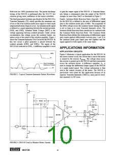
FIGURE 2. Isolation Mode Rejection and Transient Immunity Test Circuit.
9
®
ISO130

 BB [ BURR-BROWN CORPORATION ]