Both tests are 100% production tests. The partial discharge
testing of the ISO130 is performed after the UL1577 test
criterion giving more confidence in the barrier reliability.
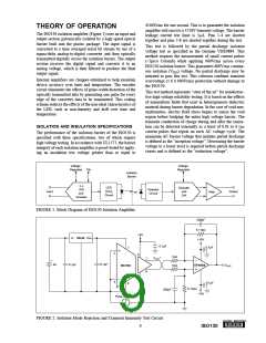
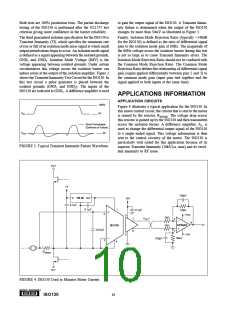
to gain the output signal of the ISO130. A Transient Immu-
nity failure is determined when the output of the ISO130
changes by more than 50mV as illustrated in Figure 3.
The third guaranteed isolation specification for the ISO130 is
Transient Immunity (TI), which specifies the minimum rate
of rise or fall of an isolation mode noise signal at which small
output perturbations begin to occur. An isolation mode signal
is defined as a signal appearing between the isolated grounds,
GND1 and GND2. Isolation Mode Voltage (IMV) is the
voltage appearing between isolated grounds. Under certain
circumstances this voltage across the isolation barrier can
induce errors at the output of the isolation amplifier. Figure 2
shows the Transient Immunity Test Circuit for the ISO130. In
this test circuit a pulse generator is placed between the
isolated grounds (GND1 and GND2). The inputs of the
ISO130 are both tied to GND1. A difference amplifier is used
Finally, Isolation Mode Rejection Ratio (typically >140dB
for the ISO130) is defined as the ratio of differential signal
gain to the isolation mode gain at 60Hz. The magnitude of
the 60Hz voltage across the isolation barrier during this test
is not so large as to cause Transient Immunity errors. The
Isolation Mode Rejection Ratio should not be confused with
the Common Mode Rejection Ratio. The Common Mode
Rejection Ratio defines the relationship of differential signal
gain (signal applied differentially between pins 2 and 3) to
the common mode gain (input pins tied together and the
signal applied to both inputs at the same time).
APPLICATIONS INFORMATION
APPLICATION CIRCUITS
1000V
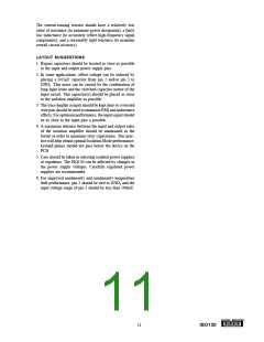
Figure 4 illustrates a typical application for the ISO130. In
this motor control circuit, the current that is sent to the motor
is sensed by the resistor, RSENSE. The voltage drop across
this resistor is gained up by the ISO130 and then transmitted
across the isolation barrier. A difference amplifier, A2, is
used to change the differential output signal of the ISO130
to a single ended signal. This voltage information is then
sent to the control circuitry of the motor. The ISO130 is
particularly well suited for this application because of its
superior Transient Immunity (10kV/µs, max) and its excel-
lent immunity to RF noise.
VIM
0V
50mV Perturbation
(Definition of Failure)
VOUT
0V
FIGURE 3. Typical Transient Immunity Failure Waveform.
HV+
• • •
V +
150pF
In 78L05 Out
+5V
0.1µF
0.1µF
2
1
ISO130
4
0.1µF
10kΩ
+15V
8
5
+
2kΩ
2kΩ
VOUT
7
6
2
3
6
OPA604
0.01µF
3
–15V
10kΩ
150pF
+
–
• • •
RSENSE
• • •
HV–
FIGURE 4. ISO130 Used to Monitor Motor Current.
®
ISO130
10

 BB [ BURR-BROWN CORPORATION ]