[1]
IEC/EN/DIN EN 60747-5-2 Insulation Characteristics
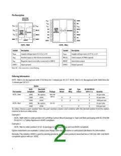
Description
Symbol
HCPL-7860 HCPL-786J
Unit
Installation classification per DIN VDE 0110/1.89, Table 1
for rated mains voltage ꢅ 300 Vrms
I - IV
I - III
I - III
I - II
I - IV
I - IV
I - IV
I - III
for rated mains voltage ꢅ 450 Vrms
for rated mains voltage ꢅ 600 Vrms
for rated mains voltage ꢅ 1000 Vrms
Climatic Classification
40/85/21
2
40/85/21
2
Pollution Degree (DIN VDE 0110/1.89)
Maximum Working Insulation Voltage
VIORM
VPR
891
1230
2306
Vpeak
Vpeak
Input to Output Test Voltage, Method b [2]
VIORM x 1.875=VPR, 100% Production Test with tm=1 sec,
Partial discharge < 5 pC
1670
Input to Output Test Voltage, Method a[2]
VIORM x 1.6=VPR, Type and Sample Test, tm=10 sec,
Partial discharge < 5 pC
VPR
1425
6000
1968
8000
Vpeak
Vpeak
Highest Allowable Overvoltage(Transient Overvoltage tini = 60 sec)
VIOTM
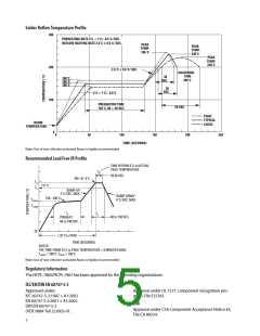
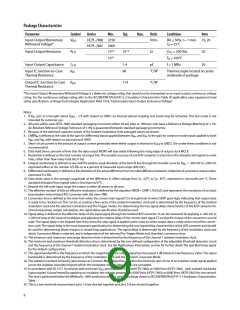
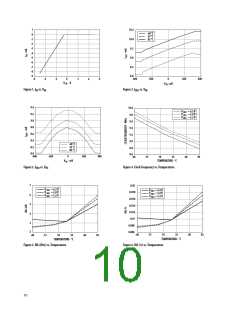
Safety-limiting values - maximum values allowed in the event of a failure.
Case Temperature
Input Current [3]
Output Power [3]
TS
175
400
600
175
400
600
°C
mA
mW
IS, INPUT
PS, OUTPUT
Insulation Resistance at TS, VIO = 500 V
RS
>109
>109
ꢆ
Notes:
800
700
600
500
400
300
1. Insulation characteristics are guaranteed only within the safety maximum ratings, which must
be ensured by protective circuits within the application. Surface Mount Classifications is Class
A in accordance with CECC00802.
2. Refer to the optocoupler section of the Isolation and Control Components Designer’s Catalog,
under Product Safety Regulations section, (IEC/EN/DIN EN 60747-5-2) for a detailed descrip-
tion of Method a and Method b partial discharge test profiles.
P
(mWꢀ
S
IS (mAꢀ
3. Refer to the following figure for dependence of P and I on ambient temperature.
S
S
200
100
0
0
25 50 75 100 125 150 175 200
TS - CASE TEMPERATURE - o
C
Insulation and Safety Related Specifications
Option 300 - surface mount classification is Class A in accordance with CECC 00802.
Parameter
Symbol
DIP-8
SO-16
Units
Conditions
Minimum External Air Gap L(101)
(Clearance)
7.4
8.3
mm
Measured from input terminals to output terminals,
shortest distance through air.
Minimum External Tracking L(102)
(Creepage)
8.0
0.5
8.3
0.5
mm
mm
Measured from input terminals to output terminals,
shortest distance path along body.
Minimum Internal Plastic
Gap (Internal Clearance)
Through insulation distance conductor to conductor,
usually the straight line distance thickness between
the emitter and detector.
Tracking Resistance
(Comparative Tracking
Index)
CTI
>175
IIIa
>175
IIIa
V
DIN IEC 112/VDE 0303 Part 1
Isolation Group
Material Group (DIN VDE 0110, 1/89, Table 1)
6

 AVAGO [ AVAGO TECHNOLOGIES LIMITED ]