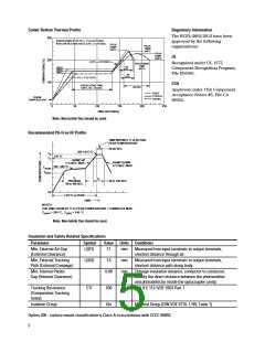
Solder Reflow Thermal Profile
Regulatory Information
The HCPL-2602/2612 have been
approved by the following
organizations:
300
PREHEATING RATE 3°C + 1°C/–0.5°C/SEC.
REFLOW HEATING RATE 2.5°C ± 0.5°C/SEC.
PEAK
TEMP.
245°C
PEAK
TEMP.
240°C
PEAK
TEMP.
230°C
UL
200
100
0
2.5°C ± 0.5°C/SEC.
Recognized under UL 1577,
Component Recognition Program,
File E55361.
SOLDERING
TIME
200°C
30
160°C
150°C
140°C
SEC.
30
SEC.
3°C + 1°C/–0.5°C
CSA
PREHEATING TIME
150°C, 90 + 30 SEC.
50 SEC.
Approved under CSA Component
Acceptance Notice #5, File CA
88324.
TIGHT
TYPICAL
LOOSE
ROOM
TEMPERATURE
0
50
100
150
200
250
TIME (SECONDS)
Note: Non-halide flux should be used.
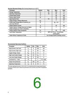
Recommended Pb-Free IR Profile
TIME WITHIN 5 °C of ACTUAL
PEAKTEMPERATURE
t
p
20-40 SEC.
260 +0/-5 °C
T
T
p
217 °C
L
RAMP-UP
3 °C/SEC. MAX.
RAMP-DOWN
6 °C/SEC. MAX.
150 - 200 °C
T
smax
T
smin
t
s
t
L
60 to 150 SEC.
PREHEAT
60 to 180 SEC.
25
t 25 °C to PEAK
TIME
NOTES:
THE TIME FROM 25 °C to PEAK TEMPERATURE = 8 MINUTES MAX.
= 200 °C, T = 150 °C
T
smax
smin
Note: Non-halide flux should be used.
Insulation and Safety Related Specifications
Parameter
Symbol
Value Units Conditions
Min. External Air Gap
(External Clearance)
L(I01)
7.1
mm
mm
mm
Measured from input terminals to output terminals,
shortest distance through air.
Min. External Tracking
Path (External Creepage)
L(I02)
CTI
7.4
Measured from input terminals to output terminals,
shortest distance path along body.
Min. Internal Plastic
Gap (Internal Clearance)
0.08
Through insulation distance, conductor to conductor,
usually the direct distance between the photoemitter
and photodetector inside the optocoupler cavity.
Tracking Resistance
(Comparative Tracking
Index)
200
IIIa
V
DIN IEC 112/ VDE 0303 Part 1
Isolation Group
Material Group (DIN VDE 0110, 1/ 89, Table 1)
Option 300 - surface mount classification is Class A in accordance with CECC 00802.
5

 AVAGO [ AVAGO TECHNOLOGIES LIMITED ]