different circuit configuration
could make tPHL < tPLH, in which
case NOR gates would be pre-
ferred. If it is not known whether
tPHL > tPLH or tPHL < tPLH, or if the
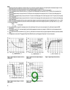
drive conditions may vary over the the exact figure depends on the
boundary for these conditions, the particular application (RS232,
exclusive-OR flip-flop of Figure (d) RS422, T-1, etc.).
should be used.
the PWD (in ns) by the minimum
pulse width (in ns) being
transmitted. Typically, PWD on
the order of 20-30% of the
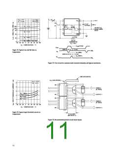
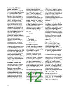
both the clock and the data lines
being sent through optocouplers.
The figure shows data and clock
signals at the inputs and outputs
of the optocouplers. To obtain the
maximum data transmission rate,
both edges of the clock signal are
being used to clock the data; if
only one edge were used, the
clock signal would need to be
twice as fast.
minimum pulse width is tolerable;
Propagation delay skew, tPSK, is an
RS-422 and RS-423
important parameter to consider
in parallel data applications
where synchronization of signals
on parallel data lines is a concern.
If the parallel data is being sent
through a group of optocouplers,
differences in propagation delays
will cause the data to arrive at the
outputs of the optocouplers at
different times. If this difference
in propagation delays is large
enough, it will determine the
maximum rate at which parallel
data can be sent through the
optocouplers.
Line drivers designed for RS-422
and RS-423 generally provide
adequate voltage and current for
operating the HCPL-2602/12. Most
drivers also have characteristics
allowing the HCPL-2602/12 to be
connected directly to the driver
terminals. Worst case drive
conditions, however, would
require current shunting to
prevent overstress of the HCPL-
2602/12.
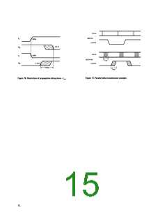
Propagation delay skew
represents the uncertainty of
where an edge might be after
being sent through an
optocoupler. Figure 17 shows that
there will be uncertainty in both
the data and the clock lines. It is
important that these two areas of
uncertainty not overlap,
otherwise the clock signal might
arrive before all of the data
outputs have settled, or some of
the data outputs may start to
change before the clock signal has
arrived. From these
considerations, the absolute
minimum pulse width that can be
sent through optocouplers in a
parallel application is twice tPSK. A
cautious design should use a
slightly longer pulse width to
ensure that any additional
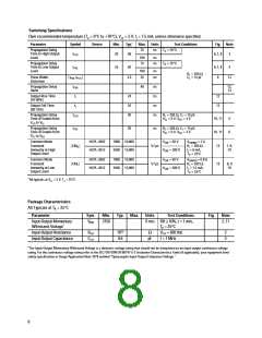
Propagation Delay, Pulse-Width
Distortion and Propagation Delay Skew
Propagation delay is a figure of
merit which describes how quickly
a logic signal propagates through a
system. The propagation delay
from low to high (tPLH) is the
amount of time required for an
input signal to propagate to the
output, causing the output to
change from low to high. Similarly,
the propagation delay from high to
low (tPHL) is the amount of time
required for the input signal to
propagate to the output, causing
the output to change from high to
low (see Figure 6).
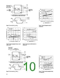
Propagation delay skew is defined
as the difference between the
minimum and maximum
propagation delays, either tPLH or
tPHL, for any given group of
optocouplers which are operating
under the same conditions (i.e.,
the same drive current, supply
voltage, output load, and
uncertainty in the rest of the
circuit does not cause a problem.
operating temperature). As
illustrated in Figure 16, if the
inputs of a group of optocouplers
are switched either ON or OFF at
the same time, tPSK is the
difference between the shortest
propagation delay, either tPHL or
tPHL, and the longest propagation
The tPSK specified optocouplers
offer the advantages of
guaranteed specifications for
propagation delays, pulse-width
distortion and propagation delay
skew over the recommended
temperature, input current, and
power supply ranges.
Pulse-width distortion (PWD)
results when tPLH and tPHL differ in
value. PWD is defined as the
difference between tPLH and tPHL
and often determines the
maximum data rate capability of a
transmission system. PWD can be
expressed in percent by dividing
delay, either tPLH or tPHL
.
As mentioned earlier, tPSK can
determine the maximum parallel
data transmission rate. Figure 17
is the timing diagram of a typical
parallel data application with
14

 AVAGO [ AVAGO TECHNOLOGIES LIMITED ]