Using the HCPL-2602/ 12 Line
Receiver Optocouplers
interfere with circuit perform-
ance because the regulator
inputs are then connected in
ANTI-SERIES; however, because
of the higher steady-state termina-
tion voltage, in comparison to the
single HCPL-2602/12 termination,
the forward current in the
substrate diode is lower and
consequently there is less junction
charge to deal with when
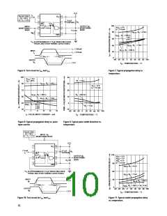
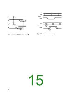
clamps the line voltage. At longer
line lengths, tPLH increases faster
than tPHL since the switching
threshold is not exactly halfway
between asymptotic line
conditions. If optimum data rate
is desired, a series resistor and
peaking capacitor can be used to
equalize tPLH and tPHL. In general,
the peaking capacitance should be
as large as possible; however, if it
is too large it may keep the
The primary objectives to fulfill
when connecting an optocoupler
to a transmission line are to
provide a minimum, but not
excessive, LED current and to
properly terminate the line. The
internal regulator in the HCPL-
2602/12 simplifies this task.
Excess current from variable
drive conditions such as line
length variations, line driver
differences, and power supply
fluctuations are shunted by the
regulator. In fact, with the LED
current regulated, the line current
can be increased to improve the
immunity of the system to
differential-mode-noise and to
enhance the data rate capability.
The designer must keep in mind
the 60 mA input current
maximum rating of the HCPL-
2602/12 in such cases, and may
need to use series limiting or
shunting to prevent overstress.
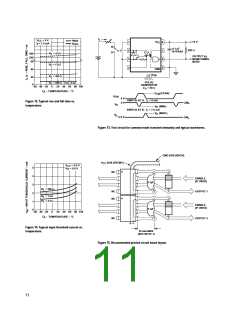
switching.
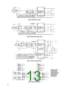
Closing switch B with A open is
done mainly to enhance common
mode rejection, but also reduces
propagation delay slightly because
line-to-line capacitance offers a
slight peaking effect. With
switches A and B both CLOSED,
the shield acts as a current return
path which prevents either input
substrate diode from becoming
reversed biased. Thus the data
rate is optimized as shown in
Figure (c).
regulator from achieving turn-off
during the negative (or zero)
excursions of the input signal. A
safe rule:
make C ≤16t
where:
C = peaking capacitance in
picofarads
t = data bit interval in
nanoseconds
Improved Noise Rejection
Use of additional logic at the
output of two HCPL-2602/12s,
operated in the split phase
termination, will greatly improve
system noise rejection in addition
to balancing propagation delays
as discussed earlier.
Polarity Reversing Drive
Design of the termination circuit
is also simplified; in most cases
the transmission line can simply
be connected directly to the input
terminals of the HCPL-2602/12
without the need for additional
series or shunt resistors. If
reversing line drive is used it may
be desirable to use two HCPL-
2602/12 or an external Schottky
diode to optimize data rate.
A single HCPL-2602/12 can also
be used with polarity reversing
drive (Figure b). Current reversal
is obtained by way of the
substrate isolation diode
(substrate to collector). Some
reduction of data rate occurs,
however, because the substrate
diode stores charge, which must
be removed when the current
changes to the forward direction.
A NAND flip-flop offers infinite
common mode rejection (CMR)
for NEGATIVELY sloped common
mode transients but requires tPHL
> tPLH for proper operation. A NOR
flip-flop has infinite CMR for
The effect of this is a longer tPHL
.
Polarity Non-Reversing Drive
This effect can be eliminated and
data rate improved considerably
by use of a Schottky diode on the
input of the HCPL-2602/12.
POSITIVELY sloped transients
but requires tPHL < tPLH for proper
operation. An exclusive-OR flip-
flop has infinite CMR for common
mode transients of EITHER
High data rates can be obtained
with the HCPL-2602/12 with
polarity non-reversing drive.
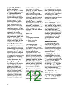
Figure (a) illustrates how a
74S140 line driver can be used
with the HCPL-2602/12 and
shielded, twisted pair or coax
cable without any additional
components. There are some
reflections due to the “active
termination,” but they do not
For optimum noise rejection as
well as balanced delays, a split-
phase termination should be used
along with a flip-flop at the output
(Figure c). The result of current
reversal in split-phase operation
is seen in Figure (c) with switches
A and B both OPEN. The coupler
polarity and operates with either
tPHL > tPLH or tPHL < tPLH
.
With the line driver and
transmission line shown in Figure
(c), tPHL > tPLH, so NAND gates are
preferred in the R-S flip-flop. A
higher drive amplitude or
12

 AVAGO [ AVAGO TECHNOLOGIES LIMITED ]