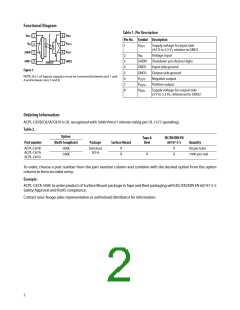
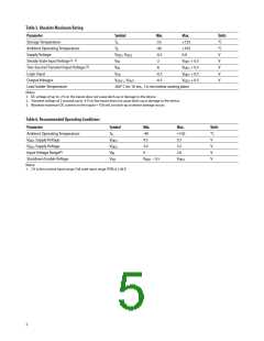
Functional Diagram
Table 1. Pin Description
8
7
VDD2
VDD1
VIN
1
2
Pin No. Symbol Description
VOUT+
1
VDD1
Supply voltage for input side
(40. V to .0. V), relative to GND1
6
5
VOUT–
GND2
SHDN
GND1
3
4
2
3
4
.
6
7
8
VIN
Voltage input
SꢀDN
GND1
GND2
VOUT-
Shutdown pin (Active ꢀigh)
Input side ground
Output side ground
Negative output
SHIELD
Figure 1.
NOTE: A ±01 F bypass capacitor must be connected between pins 1 and
4 and between pins . and 80
VOUT+ Positive output
VDD2 Supply voltage for output side
(3 V to .0. V), referenced to GND2
Ordering Information
ACPL-C87B/C87A/C87± is UL recognized with .±±± Vrms/1 minute rating per UL 1.77 (pending)0
Table 2.
Option
Tape &
Reel
IEC/EN/DIN EN
60747-5-5
Part number
(RoHS Compliant)
-±±±E
Package
Surface Mount
Quantity
ACPL-C87B
ACPL-C87A
ACPL-C87±
Stetched
SO-8
X
X
X
X
8± per tube
1±±± per reel
-.±±E
X
To order, choose a part number from the part number column and combine with the desired option from the option
column to form an order entry0
Example:
ACPL-C87A-.±±E to order product of Surface Mount package in Tape and Reel packaging with IEC/EN/DIN EN 6±747-.-.
Safety Approval and RoꢀS compliance0
Contact your Avago sales representative or authorized distributor for information0
2

 AVAGO [ AVAGO TECHNOLOGIES LIMITED ]