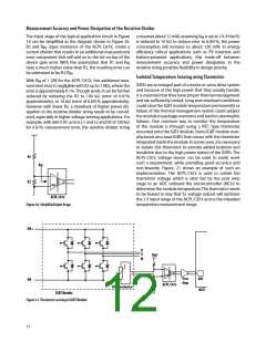
Measurement Accuracy and Power Dissipation of the Resistive Divider
The input stage of the typical application circuit in Figure consumes about 12 mW, assuming V is set at 2 V0 If the R2
IN
19 can be simplified as the diagram shown in Figure 2±0 is reduced to 1± k to reduce error to ±0±±15, the power
R2 and R , input resistance of the ACPL-C87X, create a consumption will increase to about 12± mW0 In energy
IN
current divider that results in an additional measurement efficiency critical applications such as PV inverters and
error component that will add on to the tot on top of the battery-powered applications, this trade-off between
device gain error0 With the assumption that R1 and R
measurement accuracy and power dissipation in the
resistive string provides flexibility in design priority0
IN
have a much higher value than R2, the resulting error can
be estimated to be R2/R 0
IN
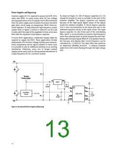
Isolated Temperature Sensing using Thermistor
With R of 1 GW for the ACPL-C87X, this additional mea-
IN
IGBTs are an integral part of a motor or servo drive system
and because of the high power that they usually handle,
it is essential that they have proper thermal management
and are sufficiently cooled0 Long term overload conditions
could raise the IGBT module temperature permanently or
failure of the thermal management system could subject
the module to package overstress and lead to catastrophic
failures0 One common way to monitor the temperature
of the module is through using a NTC type thermistor
mounted onto the IGBT module0 Some IGBT module man-
ufacturers also have IGBTs that comes with the thermistor
integrated inside the module0 In some cases, it is necessary
to isolate this thermistor to provide added isolation and
insulation due to the high power nature of the IGBTs0 The
ACPL-C87x voltage sensor can be used to easily meet
such a requirement, while providing good accuracy and
non-linearity0 Figure0 21 shows an example of such an
implementation0 The ACPL-C87x is used to isolate the
thermistor voltage which is later fed by the post amp
stage to an ADC onboard the microcontroller (MCU) to
determine the module temperature0 The thermistor needs
to be biased in way that its voltage output will optimize
the 2 V input range of the ACPL-C87x across the intended
temperature measurement range0
surement error is negligible with R2 up to 1 M, where the
error is approximately ±0150 Though small, it can be further
reduced by reducing the R2 to 1±± k (error of ±0±15
approximately), or 1± k (error of ±0±±15 approximately)0
ꢀowever with lower R2, a drawback of higher power dis-
sipation in the resistive divider string needs to be consid-
ered, especially in higher voltage sensing applications0 For
example, with 6±± V DC across L1 and L2 and R2 of 1±± k
for ±0±15 measurement error, the resistive divider string
R1
RIN
+
R2
GND
ACPL-C87x
Figure 20. Simplified Input Stage.
HV+
U
V
W
Vdd
+
GND
ADC
Post
Amp
HV-
ACPL-C87x
NTC Thermistor
IGBT Module
MCU
Figure 21. Thermistor sensing in IGBT Module
12

 AVAGO [ AVAGO TECHNOLOGIES LIMITED ]