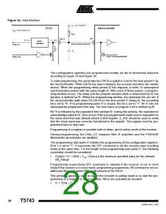
Figure 34. Data Interface
VX = 5 V to 20 V
VX = 5 V to 20 V
T5743
Microcontroller
Microcontroller
T5743
V
= 4.5 V to 5.5 V
S
V
= 4.5 V to 5.5 V
S
Rpup
Rpup
I/O
DATA
0 ... 20 V
I/O
DATA
0 V / 5 V
0 ... 20 V
Input -
Interface
0 V /I5nVput -
Interface
Serial bi-directional data line
Serial bi-directional data line
Data_In
Data_In
ID
I
D
CL
CL
Out1 mîcrocontroller
Out1 mîcrocontroller
Data_out
Data_out
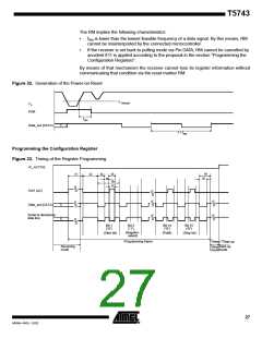
The configuration registers are programmed serially via the bi-directional data line
according to Figure 33 and Figure 34.
To start programming, the serial data line DATA is pulled to Low for the time period t1 by
the microcontroller. When DATA has been released, the receiver becomes the master
device. When the programming delay period t2 has elapsed, it emits 15 subsequent
synchronization pulses with the pulse length t3. After each of these pulses, a program-
ming window occurs. The delay until the program window starts is determined by t4, the
duration is defined by t5. Within the programming window, the individual bits are set. If
the microcontroller pulls down Pin DATA for the time period t7 during t5, the according
bit is set to “0”. If no programming pulse t7 is issued, this bit is set to “1”. All 15 bits are
subsequently programmed this way. The time frame to program a bit is defined by t6.
Bit 15 is followed by the equivalent time window t9. During this window, the equivalence
acknowledge pulse t8 (E_Ack) occurs if the just programmed mode word is equivalent to
the mode word that was already stored in that register. E_Ack should be used to verify
that the mode word was correctly transferred to the register. The register must be pro-
grammed twice in that case.
Programming of a register is possible both in sleep- and in active-mode of the receiver.
During programming, the LNA, LO, lowpass filter IF-amplifier and the FSK/ASK
Manchester demodulator are disabled.
The programming start pulse t1 initiates the programming of the configuration registers.
If bit 1 is set to “1”, it represents the OFF-command to set the receiver back to polling
mode at the same time. For the length of the programming start pulse t1, the following
convention should be considered:
•
t1(min) < t1 < 5632 PꢀTClk: t1(min) is the minimum specified value for the relevant
BR_Range
Programming respectively OFF-command is initiated if the receiver is not in reset
mode.If the receiver is in reset mode, programming respectively Off-command is not ini-
tiated and the reset marker RM is still present at Pin DATA.
This period is generally used to switch the receiver to polling mode or to start the pro-
gramming of a register. In reset condition, RM is not cancelled by accident.
•
t1 > 7936 P TClk
28
T5743
4569A–RKE–12/02

 ATMEL [ ATMEL ]