B10011S
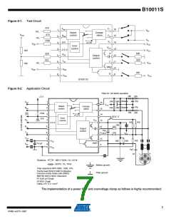
Figure 6-1. Test Circuit
470
F1
Asel
Bsel
ER
16
15
14
1
2
3
4
5
6
7
8
VIH
H/L
Select
control
Compa-
rators
470
VDD
F0
S+
H/L
VIL
150k
+4.3V
VDD
VCC
Error
control
VCC
H'
13
12
11
10
9
2.5 V
Rx0
VCC
VCC
VCC
1k8
580
620
220
470
Output
control
Tx0
L'
H/L
1k8
GND
VDD
VDD
VSS
2k5
S-
B10011S
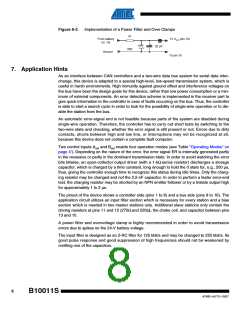
Figure 6-2. Application Circuit
Filter for 125 kbit/s operation
16k
22k
+5 V
82p
82p
47p
47p
22k
5k6
24k
Asel
Bsel
1
2
16
VDD
Select
control
Compa-
rators
24k 5k6
BCX 17
15
14
16k
150k
2n2
3
4
ER
Rx1
+4.3 V
Error
control
VCC
13
12
1k8
1k8
2.5 V
1k8
220
5
Rx0
Tx0
Output
control
+
10µ
6
7
8
270
11
10
9
40 V
V
CC
VDD
VSS
1k8
VDD
VSS
1k8
1k8
+
GND
10 µF
0µ1
H
M
L
Resistors:
MELF 0204, 1%, 0.6 W
02075, 1%, TK50
Battery ground
Filter ground
Chip capacitors NPO 0805, 1206, 10%
Ferrite bead BLM 31A601S (Murata)
Common-mode choke coils (SMD):
B82790 S0513 N201 (Siemens)
F2 2x50 µH (Vogt)
ST2001 (Vogt)
Cable LiYY 4 x 1 mm2
The implementation of a power filter and overvoltage clamp as follows is highly recommended:
7
4749D–AUTO–10/07

 ATMEL [ ATMEL ]